


6 9620 Professional OBD II Scan Tool
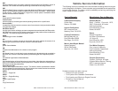
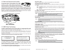
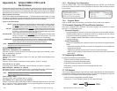
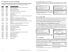
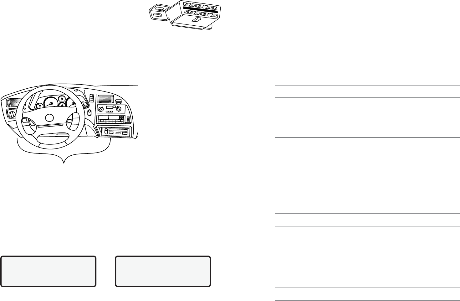
DLC Location
1.2 Data Link ConnectorandLocation
The tester communicates with the vehicle PCM via a data
link connector (DLC) also referred to as a J1962
connector. The term J1962 is taken from physical and
electrical specification number assigned by SAE (Society of
Automotive Engineers). A standardized DLC means all compliant
vehicles will use the same DLC with the generic link information available on the same
pins regardless of vehicle make or model. In addition to the connector definitions, is a
guideline on where the connector is to be located in the vehicle. This guideline states
that the DLC should be located under the dashboard on the driver side of the vehicle.
However, not all OBD II DLCs are located under the dash on the driver side. If required,
refer to vehicle service documentation for the DLC location.
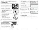
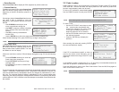
1.3 OBD II Scan Tool Hookup
The OBD II cable attached to the scan tool fits the OBD II DLC. Because the OBD II J1962
connector contains dedicated pins for power and ground, only a single cable connection is
required for both scan tool power and PCM communication.
Connect the scan tool to the DLC. This connection will provide power for the scan tool.
The DLC maintains power even when the ignition is turned off. Therefore, connection to
the battery is not required.
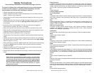
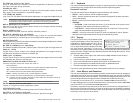
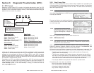
When the scan tool powers up, a series of screens are displayed. The screens start with
a Welcome screen and end with a Key Button Help screen.
The screens between the Welcome screen and the Key Button Help screen are for
tool self-tests and software ID. Refer to this software ID when contacting the Actron
technical support line with a problem. To review the key button definitions, push the
(HELP) key; otherwise, press ENTER to continue.
The scan tool requires a minimum of 8 volts to power up. If a problem occurs with power-
up, review Section 4: Help and Troubleshooting Tips.
Welcome To
The Global OBDII
SCANTOOL
Press HELP For Key |
Button Information
Press ENTER To Cont
9620 Professional OBD II Scan Tool 31
REL TPS (0 - 100%)
Relative Throttle Position is relative throttle position at normal position.
SECOND AIR (AIR_STAT: UPS, DNS or OFF)
Commanded Secondary Air Status is on newer vehicles and actuators to control pollu-
tion control.
UPS - UP STREAM module is demanding that secondary air be added at exhaust
manifolds
DNS - DOWN STREAM module is demanding secondary air be added at catalytic
converter
OFF - Module is demanding no secondary air to be added.
ST FTRMxy (-100 - 99.22%)
Short-term Fuel Trim Bank calculated value represents the short-term relation of fuel
metering on a fuel-injected engine.
NOTE: Short-term Fuel Trim calculated value that has a positive percentage is a rich fuel
trim and if a negative percentage is present the fuel trim is lean.
ST FLTRMx (-100 - 99.2%)
Short-term Fuel Trim value represents the short-term relation of fuel metering on a fuel-
injected engine.
NOTE: Short-term Fuel Trim value with a positive percentage is a rich fuel trim and if a negative
percentage is present the fuel trim is lean.
THR POS (0 - 100%)
Absolute Throttle Position is the position the throttle is located. The more the throttle is
closed the less percent shown.
THROT CMD (0 - 100%)
Commanded Throttle Actuator Control is the position of the throttle. If throttle is closed the
percent will be 0 and if wide open 100%.
TRIPS SNC CLR (0 - 255)
Number of warm-ups since diagnostic trouble codes cleared. Warm-up is when temperature
of coolant rises to at least 22°C (40°F) from engine starting and reaching a minimum tempera-
ture of 70°C (160°F). If a diesel engine the engine minimum temperature is 60°C (140°F.)
NOTE: If there is more than 255 that the engine warms up the TRIPS SNC CLR will remain
at 255.
TROUB CODE (00 00 - FF FF)
Trouble Code Parameter will give the diagnostic trouble code that caused a freeze
frame capture. This information is helpful in diagnosing the cause of a driveability. If no
freeze frame data has been captured this PID will be zero.
VEH SPEED (0 - 255K/h) or (0 - 158mph)
Vehicle Speed shows the speed the vehicle is going.
VPWR (0 - 65.535V)
Control Module Voltage is the power input to the control module.
NOTE: 42-volt vehicles may utilise multiple voltages for different systems on the vehicle.
VPWR may be significantly different than battery voltage.