


2 9620 Professional OBD II Scan Tool
Table of Contents
2.3.9 On-Board Systems ............... 17
2.3.10 Record Data .......................... 17
2.3.11 Vehicle Info ........................... 18
2.3.12 Modules Present ................... 19
2.3.13 Review Data .......................... 19
2.3.14 Print Data .............................. 20
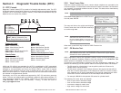
Section 3: Diagnostic Trouble
Codes (DTC) ---- 22
3.1 DTC Format .................................. 22
3.2 Code Lookup ................................ 23
3.3 Diagnostic Trouble Code Ranges 24
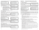
Section 4: Help and Trouble-
shooting Tips ---- 25
4.1 How to Use Help ........................... 25
4.2 Scan Tool Problems ..................... 25
4.2.1 Scan Tool does not powerup:
25
4.2.2 Scan Tool does not Link
withvehicle:........................... 25
4.2.3 One or more modules drops
the communication link: ...... 26
4.2.4 Keyboard does not function
properly: ................................ 26
4.3 Tool Self-Tests.............................. 26
4.3.1 Display Test........................... 26
4.3.2 Keyboard Test....................... 26
4.3.3 Memory Test .......................... 27
4.3.4 Printer Test ............................ 27
4.4 Technical Support ........................ 27
Appendix A: Global OBD II PID
List & Definitions 28
Appendix B:Glossary & Defini-
tions ---------------- 31
All information, illustrations and specifications contained in this manual are based
on the latest information available from industry sources at the time of publication.
No warranty (expressed or implied) can be made for its accuracy or completeness,
nor is any responsibility assumed by Actron or anyone connected with it for loss or
damages suffered through reliance on any information contained in this manual or
misuse of accompanying product. Actron reserves the right to make changes at any
time to this manual or accompanying product without obligation to notify any person
or organization of such changes.
Vehicle ServiceInformation ......3
Safety Precautions .....................4
Section 1: Vehicle Computer
Systems------------- 5
1.1 Introduction .....................................5
1.1.1 What The Computer Controls .5
1.1.2 What Has Not Changed ..........5
1.1.3 Computer Control System ......5
1.2 Data Link ConnectorandLocation . 6
1.3 OBD II Scan Tool Hookup ................6
1.3.1 Keyboard .................................7
1.3.2 Display .....................................7
1.3.3 Lists, Menus, and Questions ...7
1.4 Tool Setup .......................................8
1.4.1 Changing Measurement Units 8
1.4.2 Changing Display Contrast .....8
1.4.3 Displaying Tool Information ....9
1.4.4 Program Mode .........................9
1.5 Personal Computer (PC) and
PrinterInterface..............................9
1.6 Replacing the Battery .....................9
1.7 AC Adapter ......................................9
Section 2: Diagnosing with
theScan Tool ---- 10
2.1 Preliminary Checks ..................... 10
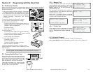
2.2 Connecting the Scan Tool ............ 10
2.3 OBD II Functions List .....................11
2.3.1 I/M Readiness ........................11
2.3.2 Read Codes .......................... 12
2.3.3 Pending Codes ..................... 12
2.3.4 Erase Codes ......................... 13
2.3.5 View Data .............................. 13
2.3.6 View Freeze Data ................. 15
2.3.7 O2 Monitor Test ..................... 15
2.3.8 Non-Continuous Tests .......... 16
9620 Professional OBD II Scan Tool 35
M/T:
Manual transmission or manual transaxle.
MAF:
Mass Air Flow Sensor. Measures the amount and density of air entering the engine and
sends a frequency or voltage signal to the PCM. The PCM uses this signal in its fuel delivery
calculations.
MAP:
Manifold Absolute Pressure Sensor. Measures intake manifold vacuum or pressure and
sends a frequency or voltage signal (depending on sensor type) to the PCM. This gives the
PCM information on engine load for control of fuel delivery, spark advance, and EGR flow.
MAT:
Manifold Air Temperature sensor. A resistance sensor in the intake manifold that sends a
voltage signal to the PCM indicating the temperature of the incoming air. The PCM uses this
signal for fuel delivery calculations.
MIL:
Malfunction Indicator Lamp. The MIL is most commonly known as the Check Engine or
Service Engine Soon light. A required on-board indicator to alert the driver of an emission-
related malfunction.
Monitor:
A test performed by the on-board computer to verify proper operation of emission related
systems or components.
MPFI or MFI:
Multi-Port Fuel Injection. MPFI is a fuel injection system using one (or more) injector(s) for
each cylinder. The injectors are mounted in the intake manifold, and fired in groups rather
than individually.
NOx:
Oxides of Nitrogen. A pollutant. The EGR system injects exhaust gases into the intake
manifold to reduce these gases at the tailpipe.
O2S:
Oxygen Sensor. Generates a voltage of 0.6 to 1.1 volts when the exhaust gas is rich (low
oxygen content). The voltage changes to 0.4 volts or less when the exhaust gas is lean
(high oxygen content). This sensor only operates after it reaches a temperature of
approximately 349°C (660°F). O2 sensors are usually found both upstream and downstream
of the catalytic converter. The PCM uses these sensors to fine tune the air-fuel ratio and to
monitor the efficiency of the catalytic converter. See Bank 1, Bank 2, Sensor 1, Sensor 2.
ODM:
Output Device Monitor.
OBD II:
On-Board Diagnostics, Second Generation. OBD II is a U.S. Government-mandated standard
requiring all cars and light trucks to have a common data connector, connector location,
communication protocol, DTCs and code definitions.
Sensor:
Any device that reports information to the PCM. The job of the sensor is to convert a parameter
such as engine temperature into an electrical signal that the PCM can understand.
Sensor 1:
A standard term used to identify the location of oxygen sensors. Sensor 1 is located upstream
of the catalytic converter. See O2S, Bank 1, Bank 2.
Sensor 2:
A standard term used to identify the location of oxygen sensors. Sensor 2 is located
downstream of the catalytic converter. See O2S, Bank 1, Bank 2.
Solenoid:
A device consisting of an electrical coil which when energized, produces a magnetic field in
a plunger, which is pulled to a central position. A solenoid may be used as an actuator in a
valve or switch.