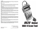
9620 Professional OBD II Scan Tool 5
Section 1: Vehicle Computer Systems
1.1 Introduction
This section describes the engine computer control system, types of sensors and how
the computer controls engine fuel delivery, idle speed and timing. Additional information
may be found in the technical support books at your local library or auto parts store. The
more known about the computer system, the easier the problem can be diagnosed.
Computer controls were originally installed on vehicles to meet federal government
regulations for lower emission levels and improved fuel economy. This began in the early
1980s when basic mechanical systems were no longer able to accurately control key
engine parameters. A computer could be programmed to control the engine under various
operating conditions, making the engine more reliable. While these early systems were
very limited in scope of their diagnostics, providing only 10-14 trouble codes, they did help
guide the vehicle repair process.
In 1994, manufacturers began equipping vehicles with a new class of computer technology
which puts more processing power under dash than ever before. It is called On-Board
Diagnostics version II, or OBD II. It is required on all vehicles sold in the US beginning
January 1, 1996 (though most domestic manufacturers introduced it earlier than required),
and offers increased system monitoring and diagnostic information. This new system stores
a library of more than 650 general trouble codes and another approximately 400
manufacturer-specific codes, all of which can be accessed with the scan tool. These codes
cover Body Systems (B-Codes), Chassis Systems (C-Codes), Communications Codes
(U-Codes), and Powertrain Systems (P-Codes). Now, basic terms are standardized and
all generic codes will share a common format and terminology that manufacturers and the
Society of Automotive Engineers (SAE) designed.
The OBD II Professional Scan Tool performs OBD II functions on ALL makes of OBD II
compliant vehicles from 1994 and up.
1.1.1 What The Computer Controls
The main control areas of the vehicle computer are fuel delivery, idle speed, spark advance,
and emissions controls. Some on-board computers may also control the transmission,
brakes, and suspension systems as well.
1.1.2 What Has Not Changed
A computer-controlled engine is very similar to the older, non-computerized engine. It is still
an internal combustion engine with pistons, spark plugs, valves, and camshaft(s). The ignition,
charging, starting, and exhaust systems are very similar as well. Test and repair of these
systems are the same as before. The technical manuals for these components provide
instruction on how to perform the tests. Additionally, compression gauges, vacuum pumps,
engine analyzers, and timing lights will continue to be used.
1.1.3 Computer Control System
The vehicle on-board computer, or Powertrain Control Module (PCM), is the heart of the
system. It is sealed in a metal box and connected to the rest of the engine by a wiring
harness. The PCM is commonly located in the passenger compartment, behind the
dashboard (kick panel position), although some manufacturers locate the PCM in the
engine compartment. The PCM is programmed by the factory. The program is a complex
list of lookup tables and instructions telling the computer how to control the engine based
on various driving conditions. It does this using sensors to monitor what is happening and
then provide feedback through a network of switches and actuators throughout the vehicle.
32 9620 Professional OBD II Scan Tool
Appendix B:Glossary & Definitions
A/C:
Air Conditioning.
A/F:
Air/Fuel ratio. The proportion of air and fuel delivered to the cylinder for combustion. For
example, an A/F ratio of 14:1 denotes 14 times as much air as fuel in the mixture. A
typical ideal A/F ratio is 14.7:1.
AC Clutch Relay:
The PCM uses this relay to energize the A/C clutch, turning the A/C system on or off.
AC Pressure Sensor:
Measures air conditioning refrigerant pressure and sends a voltage signal to the
PCM.
AC Pressure Switch:
A mechanical switch connected to the A/C refrigerant line. The switch is activated
(sending a signal to the PCM) when the A/C refrigerant pressure becomes too low.
Actuator:
Actuators such as relays, solenoids, and motors allow the PCM to control the operation
of vehicle systems.
Air Injection Reaction (AIR) System:
An emission control system operated by the PCM. During cold starts, an air pump
injects outside air into the exhaust manifold to help burn hot exhaust gases. This
reduces pollution and speeds warm-up of oxygen sensors and catalytic converters.
After the engine is warm, the air will either be dumped back to the atmosphere (or into
the air cleaner assembly) or sent to the catalytic converter.
Bank 1:
The standard way of referring to the bank of cylinders containing cylinder #1. In-line
engines have only one bank of cylinders. Most commonly used to identify the location of
oxygen sensors. See O2S, Sensor 1, Sensor 2.
Bank 2:
The standard way of referring to the bank of cylinders opposite cylinder #1. Found on V-
6, V-8, V-10, etc. and horizontally opposed engines. Most commonly used to identify the
location of oxygen sensors. See O2S, Sensor 1,Sensor 2.
BARO:
Barometric Pressure Sensor. See MAP Sensor.
Boost Control Solenoid:
A solenoid that is energized by the PCM, in order to control supercharger boost pressure.
Brake Switch Signal:
An input signal to the PCM indicating that the brake pedal is being pressed. This signal
is typically used to disengage Cruise Control systems and Torque Converter Clutch
(TCC) solenoids. See also TCC.
CAM:
Camshaft Position Sensor. Sends a frequency signal to the PCM in order to synchronize
fuel injector and spark plug firing.
CARB:
California Air Resources Board. Governing body for emissions control in California.
CKP REF:
Crankshaft Position Reference.


