1800IF - PAGE 9 OF 19
Valvcon Corporation
http://www.valvcon.com
phone: 603-249-9020 fax: 603-249-9140
CALIBRATION
The potentiometer has been calibrated at the factory. However, if re-calibration is required, proceed as follows:
1) Apply power (or use the manual override) to drive the actuator to its true closed position (clockwise rotation).
2) Unplug the potentiometer lead from the back of the motherboard (connection "S6").
3) Connect an ohmmeter to the BLACK and GREEN pot leads.
4) Loosen the cam shaft gear, raise it up above the pot shaft gear, and gently rotate it clockwise until the
feedback pot hits its stop. (NOT APPLICABLE WITH 360 POT)
5) Gently rotate the cam shaft gear counterclockwise until the ohmmeter reads 50 ohms (+/- 5 ohms). NOTE: If
you are installing a positioner with the optional 360 degree pot, adjust until the ohmmeter reads 140 ohms (+/- 5
ohms).
6) While maintaining this reading, re-engage the two gears and tighten the cam gear set screw.
7) Apply power (or use the manual override) to drive the actuator to its true open position.
8) Connect the ohmmeter to the BLACK and RED pot leads. The reading should be between 35 and 60 ohms.
(or between 120 and 160 ohms for the 360 degree pot). If the reading is not between 35 and 60 ohms, repeat the
above steps for calibrating the potentiometer.
9) Connect the feedback potentiometer plug to the motherboard connection "S6." Be sure that the locking tab
and ramp face each other. Finally, use the wire ties provided to secure the pot wires away from any rotating
components in the actuator.
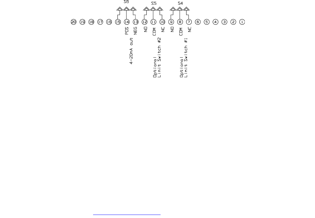
NOTE: If three additional limit switches are installed, the Potentiometer and/or Position Re-Transmit options will
not have a terminal connection on the motherboard. In this case, the user must wire directly to the three position
header at the end of the option leads.
2.1.3 POSITION RE-TRANSMIT OPTION (ORDER CODE "G")
The Position Re-transmit option uses user-supplied voltage to generate a 4-20mA signal to indicate the position of
the actuator's output shaft.
In the full clockwise position, the re-transmitter provides the minimum (4mA) signal;
in the full counterclockwise position, the potentiometer provides the maximum (20mA) signal.
For use with Cycle
Rate Regulator boards see page 12 for specific instructions.
WIRING
Re-transmit Wiring
CALIBRATION
The re-transmit option includes a potentiometer that has been calibrated at the factory. However, if re-calibration
is required:
1) Ensure the feedback loop applies a resistance of between 250 and 600 ohms.
2) Apply power (or use the manual override) to drive the actuator to its true closed position (clockwise rotation).
3) Adjust the "zero" pot on the re-transmit board until a reading of 4mA is achieved.
4) Apply power (or use the manual override) to drive the actuator to its true open position.
5) Adjust the "span" pot on the re-transmit board until a reading of 20mA is achieved.
The re-transmit option includes a potentiometer that has been calibrated at the factory. However, if re-calibration
of the potentiometer is required, follow the instructions in paragraph 2.1.2.