14 7
Monitoring charging operations
To monitor cell voltages, total pack voltage and related charging parameters during charg-
ing: Click the Cells tab.
To monitor cell internal resistances during charging: Click the Int. Res. tab.
Note: For the charger to calculate internal resistances, a) pack discharge wires must
be connected during charging and b) pack must be at less than 80% fuel level. Internal
resistances will be available for display after about three minutes of charging, and will
be periodically updated after that.
To view cell parameter graphs: View > Graphs. In the Graphs window:
To view volts: View > Volts.
To view current: View > Amps.
To view internal resistance: View > Internal Resistance.
To view fuel level: View > Fuel.
To print a graph: File > Print.
Limiting charger input current
The charger will draw up to 25A to deliver its 10A maximum output current. The high input
current is required when the input voltage must be boosted to drive packs having larger numbers
of cells in series. The charger monitors input current from the power supply, and automatically
reduces pack charge current if it determines that the power supply can’t keep up.
You can also manually limit the charger’s input current so the charger will not draw more power
than the supply can provide. If you know your power supply is rated for 3A output, for example,
you can limit the charger’s input current to 3A. This feature prevents damage to power supplies,
such as bench supplies, having low to moderate output currents. (Be aware that limiting charger
input current may increase pack charge times.) When the charger is powered from a high current
source (such as a car battery), you can override manual current limiting to provide maximum
pack charging current.
To monitor supply voltage: Click the Supply tab.
To manually set input current limiting:
1. In the
Supply tab, select the desired maximum current in the Current Limit dropdown
list.
2. Click the
Update Charger button.
To override manual input current limiting at the eld without using the Charge Control Soft-
ware:
1. Press and hold the charger’s
Mode button.
2. Connect the charger’s input cables to the power source.
3. When you see characters in the charger’s LCD display, release the
Mode button.
Note: If manual input current limiting is in effect, you must repeat this procedure each
time you apply power to the charger if you want the charger to operate at full input cur-
rent.
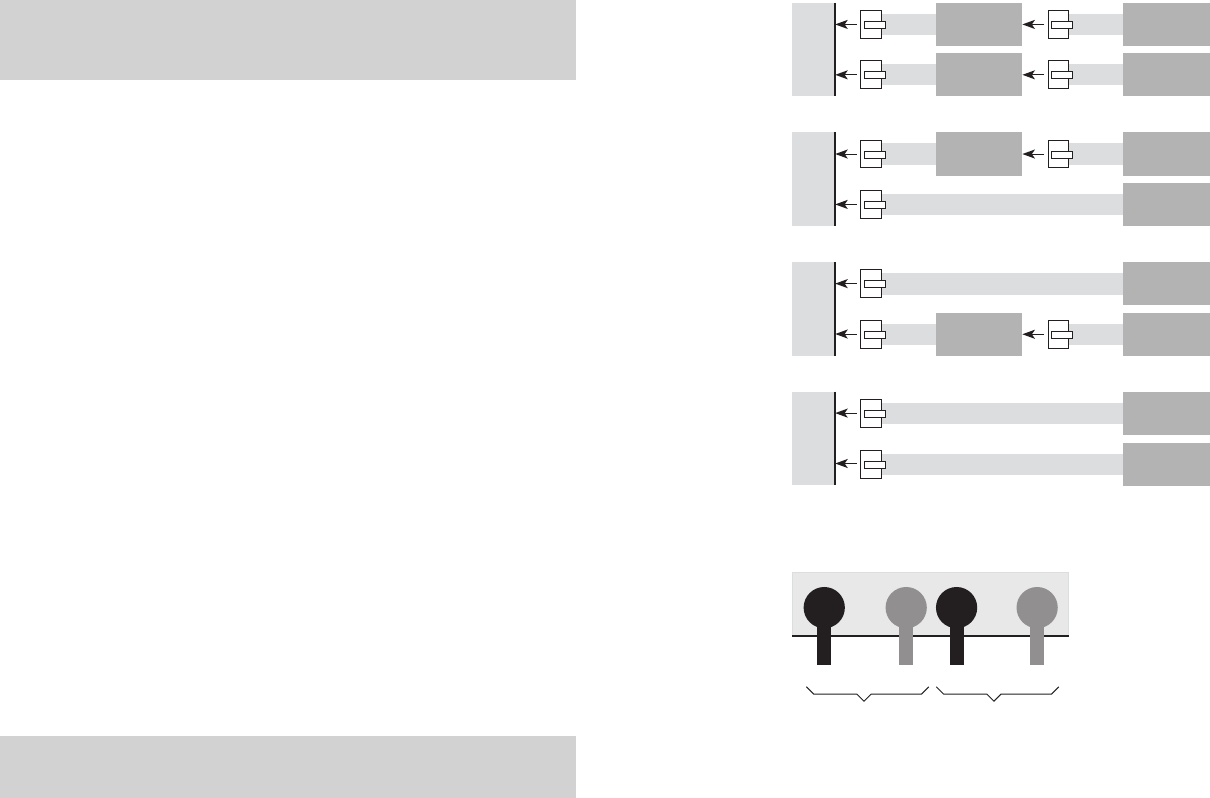
Connecting two 1s to 5s Cellpro packs
1. How you connect the Cellpro packs’ node connectors to the charger depends on the packs’
congurations.Findthecongurationsinthediagramsbelow,thenconnectasshowninthat
diagram.
2. If you are using the discharge wires during charging, connect the discharge wires into the ba
-
nana jacks as shown below.
or
If you are not using the discharge wires during charging, insert the Plug Blocker into the out
-
ermost banana jacks.
Ch2
Ch1
6-pin to 5-pin
Adapter
1s to 4s
Cellpro pack
6-pin to 5-pin
Adapter
1s to 4s
Cellpro pack
Ch2
Ch1
5s
Cellpro pack
6-pin to 5-pin
Adapter
1s to 4s
Cellpro pack
Ch2
Ch1
5s
Cellpro pack
6-pin to 5-pin
Adapter
1s to 4s
Cellpro pack
Ch2
Ch1
5s
Cellpro pack
5s
Cellpro pack
+ –– +
From Ch1 pack From Ch2 pack
1
2


