D
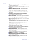
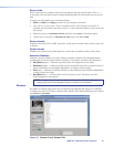
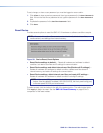
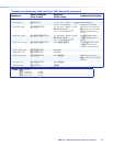
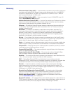
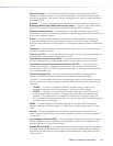
IR IN — Connect a remote IR receiver to this 3-pole 3.5 mm captive screw connector
to extend the range of the hand control.
+
S
IR Receiver
IR IN
G
Figure 6. IR In Wiring
E
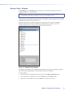
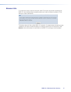
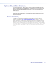
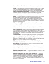
RS-232 connector (optional) — Connect a host computer or control system to the
RS-232 connector or to the local device if pass-through mode is used. Use this port to
send SIS commands to the SMD101 for device configuration and control. The default
protocol for this port is 9600 baud rate, no parity bit, 8 data bits, 1 stop bit, and no flow
control (handshaking).
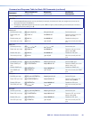
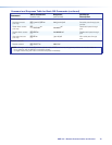
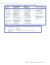
• For information on SIS commands, see Remote Communication and Control on
page57.
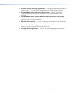
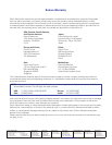
• See figure 7 below, to wire the RS-232 connector.
Ground
Tx
Rx
Receive
Transmit
Device Pins
Pins
G
Figure 7. RS-232 Connector Wiring
F
Reset button and LED — The reset button is used to return the SMD101 to partial
or complete factory condition. The reset LED provides the status of the reset. The
SMD101 has three reset modes (see SMD101 Rear Panel Reset on the following
page).
G
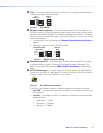
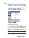
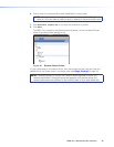
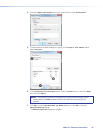
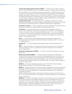
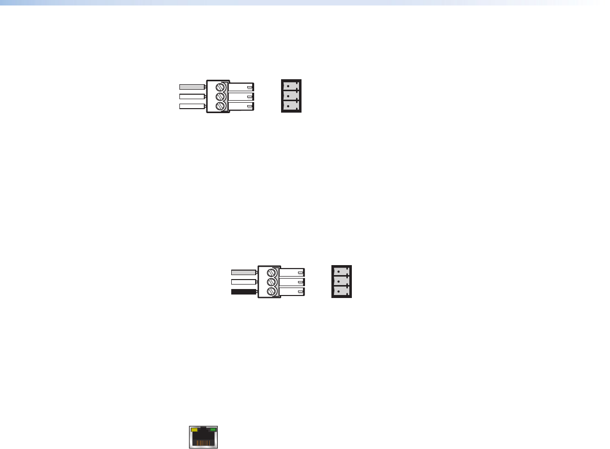
RJ-45 LAN connector — Connect one end of an RJ-45 cable to the LAN (Ethernet)
connector on the SMD101 (see figure 8). Connect the other end of the RJ-45 cable to
a router or switch to connect the SMD101 to a network.
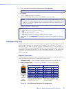
Figure 8. RJ-45 Ethernet Connector
The LEDs on the Ethernet connector indicate the status of the network connection.
• Link LED — This green LED lights when the SMD101 is properly connected to an
active network.
• Act LED — This amber LED blinks in a pattern to indicate the connected network
speed as follows:
• Three blinks — 1 Gbps
• Two blinks — 100 Mbps
• One blink — 10 Mbps
SMD101 • Panels and Cabling 11