Mobile Base Installation Guide
LIST OF FIGURES
iv
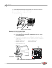
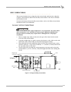
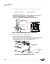
Figure 1-22: Attach the Temperature Sensor Wires to the
Breakout Board
. . . . . . . . . . . . . . . . . . . . . . . . . . . . . . . . . . . .1-16
Figure 1-23: Secure the Input Power Cable and Cable Tie . . . . . . . . . . .1-16
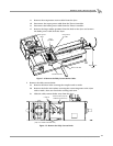
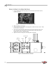
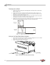
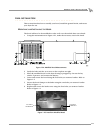
Figure 1-24: Modified Hood Measurements . . . . . . . . . . . . . . . . . . . . . . .1-17
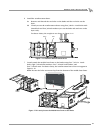
Figure 1-25: Install the Modified Hood . . . . . . . . . . . . . . . . . . . . . . . . . . .1-17
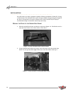
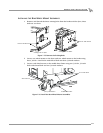
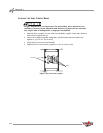
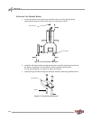
Figure 1-26: Ground Hook Placement . . . . . . . . . . . . . . . . . . . . . . . . . . . .1-18
Figure 1-27: Install the Ground Hook. . . . . . . . . . . . . . . . . . . . . . . . . . . . .1-18
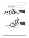
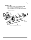
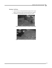
Figure 1-28: Secure the Dyno to the Rear Ground Hooks . . . . . . . . . . . .1-19
Figure 1-29: Secure the Dyno to the Front Ground Hook . . . . . . . . . . . .1-19
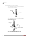
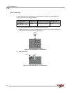
Figure A-1: Red Head Anchor—Drill the Hole . . . . . . . . . . . . . . . . . . . . . . .A-2
Figure A-2: Red Head Anchor—Insert the Anchor. . . . . . . . . . . . . . . . . . . .A-2
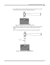
Figure A-3: Red Head Anchor—Drive the Anchor Flush . . . . . . . . . . . . . . .A-3
Figure A-4: Red Head Anchor—Expand the Anchor . . . . . . . . . . . . . . . . . .A-3