Mobile Base Installation Guide
CHAPTER 1
Eddy Current Brake
1-16
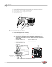
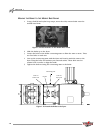
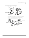
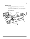
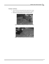
6 Attach the temperature sensor cable to the Breakout board. The temperature
sensor cable has five wires which connect to the wiring block labeled TEMP.
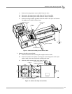
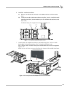
7 Replace the Breakout board cover and secure the Breakout board and cover to
the dyno frame using the four screws you removed earlier.
8 Coil the excess temperature sensor cable and secure with a cable tie.
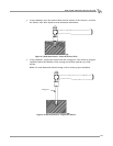
Figure 1-22: Attach the Temperature Sensor Wires to the Breakout Board
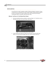
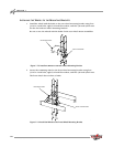
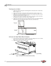
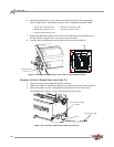
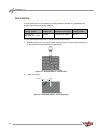
SECURING THE INPUT POWER CABLE AND CABLE TIE
1 Insert the input power cable through the cable tie.
2 Tighten the cable tie around the input power cable and trim the excess cable tie.
3 Secure the cable tie to the existing hole on the bottom of the front wheel
mounting bracket using a 1/4-20 x 1/2-inch button-head screw.
Figure 1-23: Secure the Input Power Cable and Cable Tie
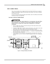
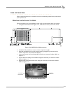
• Green wire connects to G1 • White wire connects to W1
• Black wire connects to B1 • Red wire connects to R1
• Ground wire connects to S1
temp
breakout board
and cover
screw
cable tie
input power cable
front wheel mounting
bracket