CHASSIS
3-27
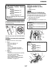
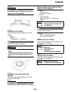
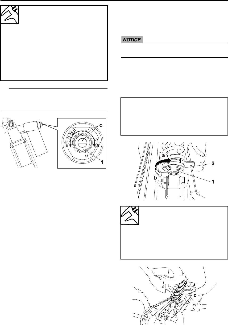
TIP
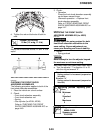
Make sure that the position indicator marks “c”
are aligned when the shock absorber is set to
the standard setting.
▲▲▲▲▲▲▲▲▲▲▲▲▲▲▲▲▲▲▲▲▲▲▲▲▲▲▲▲▲▲
EAS4D3F006
CHECKING THE REAR SHOCK ABSORBER
ASSEMBLY
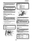
1. Place the vehicle on a level surface.
2. Check:
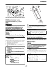
• Rear shock absorber rod
• Rear shock absorber
•Spring
• Gas cylinder
Refer to “CHECKING THE REAR
SHOCK ABSORBER ASSEMBLY” on
page 4-52.
3. Check:
• Operation
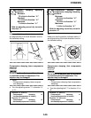
Pump the rear shock absorber assembly
up and down several times.
Unsmooth operation → Replace rear
shock absorber assembly.
Refer to “REAR SHOCK ABSORBER
ASSEMBLY” on page 4-51.
EAS29330
ADJUSTING THE REAR SHOCK
ABSORBER ASSEMBLY (for 4D3D)
1. Adjust:
• Spring preload
ECA4D3F006
Never attempt to turn the adjusting nut
beyond the maximum or minimum setting.
▼▼▼▼▼▼▼▼▼▼▼▼▼▼▼▼▼▼▼▼▼▼▼▼▼▼▼▼▼▼
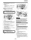
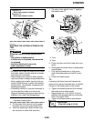
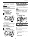
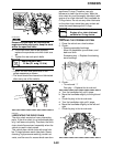
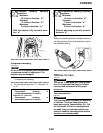
a. Elevate the rear wheels by placing a suit-
able stand under the frame.
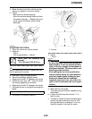
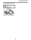
b. Loosen the locknut “1”.
c. Turn the adjusting nut “2” in direction “a” or
“b”.
Compression damping (fast com-
pression damping) adjusting
positions
Minimum
4 turns in direction: “b”*
Standard
2 turns in direction: “b”*
Maximum
0 turns in direction: “b”*
* With the adjusting bolt fully turned-in
direction “a”
Direction “a”
Spring preload is increased (suspension
is harder).
Direction “b”
Spring preload is decreased (suspension
is softer).
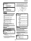
Spring preload adjusting length
“c”
Minimum
234.0 mm (9.21 in)
Standard
230.0 mm (9.06 in)
Maximum
222.0 mm (8.74 in)


