


© 2000 Directed Electronics, Inc. Vista, CA 3
what is included
table of contents
What is Included . . . . . . . . . . . . . . . . . . . . . 3
Warning! Safety First . . . . . . . . . . . . . . . . . . 4
Installation Points to Remember . . . . . . . . . . 5
Before Beginning the Installation . . . . . . . . 5
Finding the Tachometer Wire. . . . . . . . . . . . 5
Finding the Wait-to-Start Bulb Wire for Diesels. 6
After the Installation . . . . . . . . . . . . . . . . 6
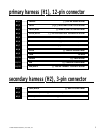
Primary Harness (H1), 12-Pin Connector . . . . . 7
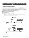
Secondary Harness (H2), 3-Pin Connector . . . . 7
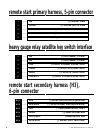
Remote Start Primary Harness, 5-Pin Connector . 8
Heavy Gauge Relay Satellite . . . . . . . . . . . . . 8
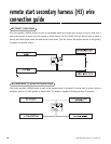
Remote Start Secondary Harness (H3),
6-Pin Connector . . . . . . . . . . . . . . . . . . . . . . 8
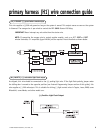
Primary Harness (H1) Wire Connection Guide . 13
Secondary Harness (H2) Wire Connection Guide. 13
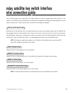
Relay Satellite Key Switch Interface
Wire Connection Guide . . . . . . . . . . . . . . . . 15
Remote Start Start Secondary Harness (H3)
Wire Connection Guide . . . . . . . . . . . . . . . . 16
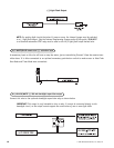
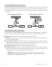
Neutral Safety Switch Interface . . . . . . . . . . 18
Testing the Neutral Safety Switch . . . . . . . . 18
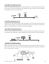
Bypassing GM Vehicle Anti-Theft Systems (VATS) . 21
1995 and Newer Vehicle Anti-Theft Systems
(Immobilizers) . . . . . . . . . . . . . . . . . . . . . . 22
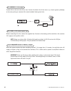
Plug-In LED and Valet/Program Switch . . . . . . 23
Programmer Interface, 3-Pin Black Connector . 23
Shock Sensor Harness, 4-Pin Connector . . . . . 24
Tach Learning. . . . . . . . . . . . . . . . . . . . . . . 25
Door Lock Harness (H4) Wire Connection Guide . 25
Positive-Triggered, Relay Driven
Systems (Type A) . . . . . . . . . . . . . . . . . . 26
Negative-Triggered, Relay Driven
Systems (Type B) . . . . . . . . . . . . . . . . . . 27
Reversing Polarity System (Type C) . . . . . . . 27
Adding One or More After-Market
Actuators (Type D) . . . . . . . . . . . . . . . . . 28
Electrically Activated Vacuum (Type E) . . . . 29
One-Wire System, (Type F) . . . . . . . . . . . . 29
Type G: Positive (+) Multiplex . . . . . . . . . . 30
Type H: Negative (-) Multiplex. . . . . . . . . . 31
Programming Jumpers . . . . . . . . . . . . . . . . . 32
Tach Threshold On/Off . . . . . . . . . . . . . . . 32
Light Flash (+)/(-) . . . . . . . . . . . . . . . . . 32
Transmitter/Receiver Learn Routine. . . . . . . . 33
Transmitter Configurations. . . . . . . . . . . . . . 35
Standard Configuration. . . . . . . . . . . . . . . 35
Single Button Arm/Disarm Configuration . . . 35
Multi-Level Security Arming . . . . . . . . . . . . . 36
Operating Settings Learn Routine . . . . . . . . . 37
Feature Menus . . . . . . . . . . . . . . . . . . . . . . 39
Feature Descriptions . . . . . . . . . . . . . . . . . . 40
Menu #1 . . . . . . . . . . . . . . . . . . . . . . . . 40
Menu #2 . . . . . . . . . . . . . . . . . . . . . . . . 42
Menu #3 . . . . . . . . . . . . . . . . . . . . . . . . 43
Nuisance Prevention Circuitry. . . . . . . . . . . . 44
Valet Mode. . . . . . . . . . . . . . . . . . . . . . . . . 45
Timer Mode . . . . . . . . . . . . . . . . . . . . . . . . 45
Table of Zones . . . . . . . . . . . . . . . . . . . . . . 46
Shutdown Diagnostics . . . . . . . . . . . . . . . . . 46
Long Term Event History . . . . . . . . . . . . . . . 47
Safety Check . . . . . . . . . . . . . . . . . . . . . . . 48
Troubleshooting . . . . . . . . . . . . . . . . . . . . . 49
Alarm Troubleshooting . . . . . . . . . . . . . . . 49
Remote Start Troubleshooting . . . . . . . . . . 50
Wiring Quick Reference Guide . . . . . . . . . . . 52
■ The control module
■ An XHF receiver/antenna
■ Two four-button remote transmitters
■ A Stinger® Doubleguard® shock sensor
■ A Revenger® Soft Chirp® siren
■ The plug-in status LED
■ The plug-in Valet®/Program switch
■ A hood pinswitch
■ A relay satellite
■ A toggle (override) switch