


© 2000 Directed Electronics, Inc. Vista, CA 17
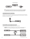
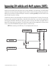
This wire MUST be connected to hood pinswitch. This input will disable or shut down the remote start when the hood
is opened. It will also trigger the security system if the hood is opened while the system is armed and report Zone 1.
This wire MUST be connected to the vehicle's brake light wire. This is the wire that shows (+) 12V when the brake
pedal is depressed. The remote start will be disabled or shut down any time the brake pedal is depressed. This
wire will also trigger the security system if the brake pedal is pressed while the system is armed and will report
Zone 1.
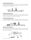
This input provides the module with information about the engine's revolutions per minute (RPMs). It can be
connected to the negative side of the coil in vehicles with conventional coils. In multi-coil and high energy igni-
tion systems locating a proper signal may be more difficult. Once connected, you must teach the system the tach
signal. (See the Internal Programming Jumpers section of this guide.)
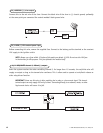
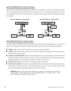
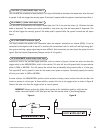
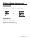
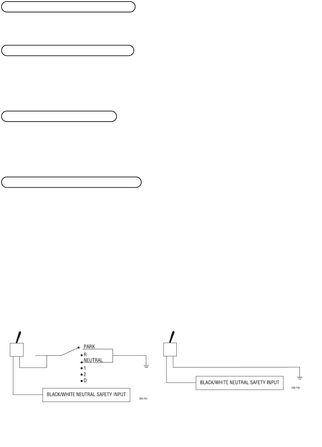
Connect this wire to the provided toggle (override) switch as shown in figure A. Connect the other wire from the
toggle switch to the PARK/NEUTRAL switch in the vehicle. This wire will test with ground with the gear selector
either in PARK or NEUTRAL. This will prevent the vehicle from accidentally being started while in a drive gear.
This input MUST rest at ground in order for the remote start system to operate. Connected properly the vehicle
will only start while in PARK or NEUTRAL.
In some vehicles, the PARK/NEUTRAL position switch activates a factory starter lock out that will not allow the
starter to operate in a drive gear. In these vehicles, connect this wire to the toggle switch as shown in figure B.
Connect the other wire from the toggle switch to chassis ground.
IMPORTANT! Always perform the Safety Check section of this installation guide to verify that the
vehicle cannot be started in ANY drive gear and that the override switch is functioning properly.
Figure A Figure B
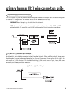
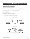
H3/6 BLACK/WHITE neutral safety switch input
H3/5 VIOLET/WHITE tachometer input
H3/4 BROWN (+) brake switch input, zone 1
H3/3 GRAY (-) hood pinswitch input, zone 1