


3 Setting up the Receiver
16 Trimble R7/R8 GPS Receiver User Guide
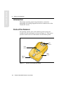
Trimble R7 Operation
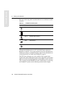
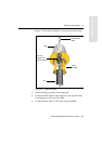
Each port on the top panel is marked with an icon to indicate its main
function.
The power/serial data ports are all 7 pin 0-shell Lemo connectors.
Both Port 2 and Port 3 can accept external power. For information on
default port settings, see Default Settings, page 85. For information on
connector pinouts, see Cables and Connectors, page 91.
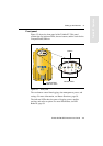
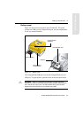
The TNC port connectors are color-coded for easy system setup.
Connect the yellow GPS antenna cable to the yellow TNC port marked
GPS, and connect the blue Range Pole antenna (RPA) cable to the blue
TNC connector marked RADIO. For more information on connecting
the Trimble R7 system, see the following sections in this chapter.
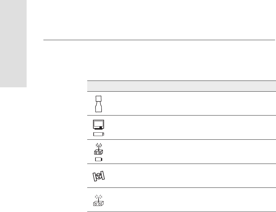
Table 3.1 Trimble R7 receiver ports
Icon Name Connections
Port 1 Trimble controller, event marker, or computer
Port 2 Power in, computer, 1PPS, or event marker
Port 3 External radio, power in
GPS GPS antenna
RADIO Radio communications antenna