


19 Cables and Connectors
164 Trimble R7/R8 GPS Receiver User Guide
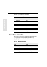
Trimble R8 Operation
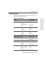
Table 19.1 describes the pinout functionality.
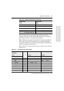
19.3 Power/Serial Data Cables
Note – Table 19.2 gives pinout information for the data-I/O cable,
(PN 18532) which is supplied with the Trimble R8 receiver
Note – Table 19.2 assumes that the cable is attached to the connector
labeled Port 2.
Table 19.1 Trimble R8 port pinouts
Pin Pinout function
Port 1 - 7-pin Lemo Port 2 - DB-9
1 Signal ground DCD
2 - Power ground RXD
3TXD TXD
4N/C DTR
5 N/C Signal ground
6 + Power in DSR
7TRXD RTS
8N/A CTS
9 N/A Ring indicator
Table 19.2 Data-I/O cable pinouts
DB-9 Female
9 Pin
DB-9 Female
9 pin
Pin Function Pin Function
1-6 DCD5_232 4 DTR5_232
2 RX5_232 3 TX5_232
3 TX5_232 2 RX5_232
4 DTR5_232 1-6 DCD5_232