


13 Setting up the Receiver
116 Trimble R7/R8 GPS Receiver User Guide
Trimble R8 Operation
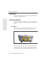
Each port or connector on the Trimble R8 receiver is marked with an
icon to indicate its main function, as shown in Table 13.1.
Port 1 is a 7-pin 0-shell LEMO connector that supports RS-232
comms and external power input. Port 1 has no power outputs.
Port 2 is a DB-9 male connector that allows for full 9-pin RS-232
comms. Port 2 does not support power in or out. For more information
on default port settings, see Chapter 18, Default Settings. For more
information on connector pinouts, see Chapter 19, Cables and
Connectors.
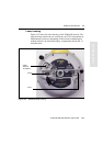
The TNC connector is for connecting a radio antenna to the
Trimble R8 internal radio. A whip “rubber duck” antenna is supplied
with the system for units with internal UHF or 900 MHz radios. This
connector is not used if you are using an external UHF radio or GSM.
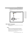
External UHF or GSM antenna
Depending on which module you have purchased, use this TNC
connection for an external antenna to enhance the UHF or GSM.
The UHF antenna is approximately 16.5 cm (6.5 inches) long, and
round. The GSM antenna is approximately 16.5 cm (6.5 inches), and
flatter than the UHF antenna. Make sure that you use the correct
antenna or the signal will be degraded.
For more information on connecting the Trimble R8, see the following
sections in this chapter.
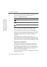
Table 13.1 Trimble R8 receiver ports
Icon Name Connections
Port 1 Device, computer, external radio, power in
Port 2 Device, computer, external radio
RADIO Radio communications antenna