


Trimble R7/R8 GPS Receiver User Guide 95
Cables and Connectors 10
Trimble R7 Operation
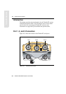
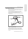
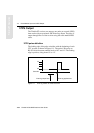
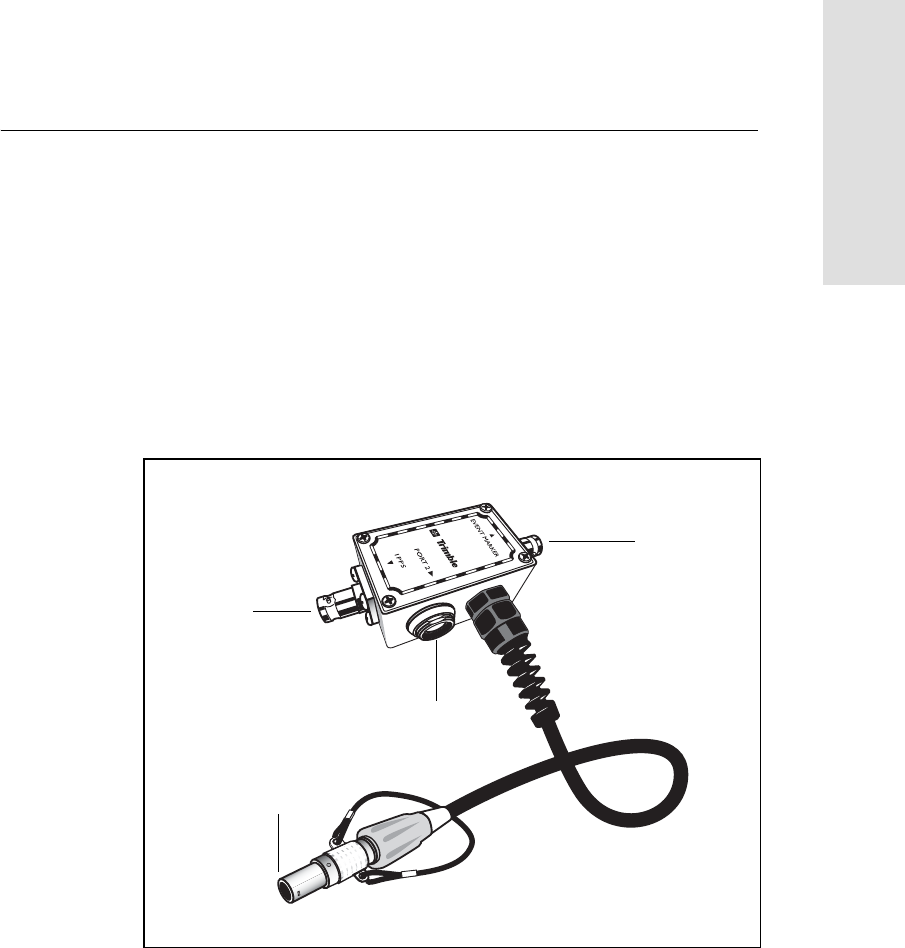
10.4 Event Marker/1PPS Cable
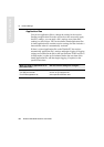
The event marker/1PPS cable shown in Figure 10.3 provides a
breakout box with two BNC (female) connectors for providing 1PPS
input and event marker output.
Connect a device that accepts 1PPS output pulses to the BNC
connector labeled 1PPS on the breakout box. Connect a device that
outputs event marker pulses to the Trimble R7, such as a
photogrammetric camera, to the BNC connector labeled Event Marker
on the breakout box.
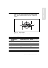
Figure 10.3 Event marker/1PPS cable
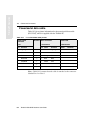
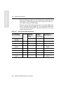
In addition, the breakout box includes a Lemo 7-pin connector to
extend serial communications and/or power on Port 2. Because the
BNC connectors are used to service the event marker and 1PPS
features, pins 4 (1PPS) and 5 (Event Marker) are inactive on the Lemo
connector.
P4
P3
P1
P2
(Event marker)
(1PPS out)
(To Port 2)
(Port 2 extension)