


Trimble R7/R8 GPS Receiver User Guide 93
Cables and Connectors 10
Trimble R7 Operation
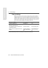
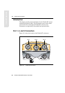
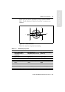
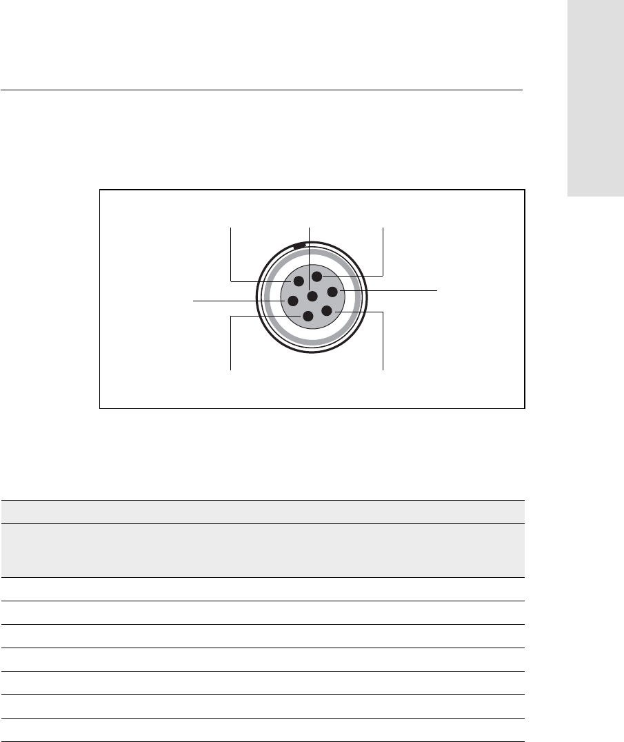
Figure 10.2 gives pinout requirements for the connector labeled
Port 1. The pin locations for the Port 2 and Port 3 connectors are
identical.
Figure 10.2 Pinout connectors
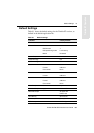
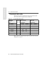
Table 10.1 describes the pinout functionality.
Table 10.1 Trimble R7 port pinouts
Pin Pinout function
Port 1 (TSC1/TSCe
controller, event, or
computer)
Port 2 (Power in,
computer, PPS, or event)
Port 3 (External radio or
power in)
1 Signal GND Signal GND Signal GND
2GND GND GND
3 TX data out (TXD1) TX data out (TXD2) TX data out (TXD3)
4 RTS1 1PPS RTS3
5 CTS1/Event 2 Event 1 CTS3
6 Power Out (+) Power In (+) Power In/Out (+)
7 Serial data in (RXD1) Serial data in (RXD2) Serial data in (RXD3)
7
1
3
6
4
2
5