


28
ELECTRICAL WIRING ROUTING
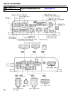
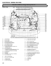
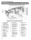
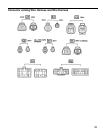
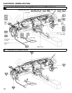
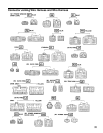
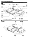
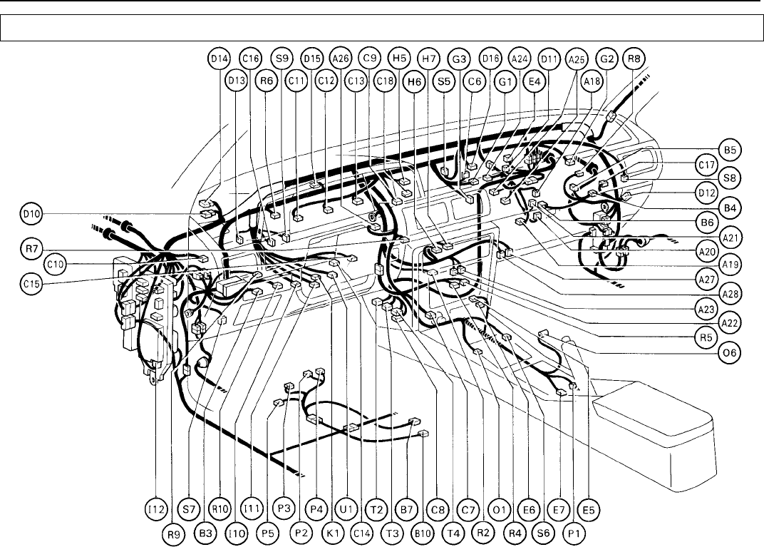
Position of Parts in Instrument Panel
A 18 A/C Acceleration Cut Amplifier C 17 Cruise Control Computer O 1 O/D Main SW and A/T Indicator
(SV) or A/C Condenser Fan C 18 Cruise Control Main SW Light
Control Amplifier (VSV) O 6 OX Sensor Sub (2VZ–FE)
A 19 A/C Amplifier (FWD) D 10 Diode (Electrical Idle–Up System)
A 20 A/C Amplifier (All–Trac/4WD) D 11 Diode (Over Drive System) P 1 Parking Brake SW
A 21 A/C Cut Relay (All–Trac/4WD) or D 12 Diode (for Interior Light System, P 2 Power Seat Motor (Front Vertical)
Compressor Control Amplifier w/ Door Lock System) P 3 Power Seat Motor (Rear Vertical)
(2VZ–FE) D 13 Diode (for Interior Light System, P 4 Power Seat Motor (Slide)
A 22 A/C System Amplifier (for Heater) w/o Door Lock System) P 5 Power Seat SW
A 23 A/C System Amplifier (for Heater) D 14 Diode (for Front Wiper System)
A 24 A/C Thermistor (3S–FE) D 15 Diode (for Rear Wiper System) R 2 Running Light Control Relay
A 25 A/C Thermistor and Diode (2VZ–FE) D 16 Door Lock Control Relay (for CANADA)
A 26 A/T Indicator (Instrument Panel) R 4 Radio and Tape Player
A 27 Air Mix Control Servo Motor E 4 ECT ECU (FWD) R 5 Radio and Tape Player
A 28 Air Vent Mode Control Servo Motor E 5 ECT ECU (All–Trac/4WD) R 6 Rear Window Defogger SW
E 6 ECT ECU (All–Trac/4WD) R 7 Rear Wiper and Washer SW (W/G)
B 3 Back Door Lock Control SW (W/G) E 7 ECT Pattern Select SW or Diff. Lock Control SW
B 4 Blower Control Relay (All–Trac/4WD)
B 5 Blower Motor G 1 Glove Box Light R 8 Recirc/Fresh Control Servo Motor
B 6 Blower Resistor G 2 Glove Box Light SW (CANADA) R 9 Remote Control Mirror SW
B 7 Buckle SW (w/ Power Seat) G 3 Glove Box Light SW (USA) R 10 Rheostat
B 10 Buckle SW (w/o Power Seat)
H 5 Hazard SW S 5 Seat Belt Warning Relay
C 6 Center Diff. Lock Indicator Light H 6 Heater Control Assembly S 6 Shift Lock Control Computer
(All–Trac/4WD) (Push SW Type) or A/C SW and S 7 Speaker Front LH
C 7 Cigarette Lighter Blower SW (Lever SW Type) S 8 Speaker Front RH
C 8 Circuit Opening Relay H 7 Heater Control Assembly S 9 Stop Light SW and Cruise Control
C 9 Clock (Push SW Type) or A/C SW and Stop SW
C 10 Clutch Start SW (M/T) Blower SW (Lever SW Type)
C 11 Combination Meter T 2 TCCS ECU (Engine ECU)
C 12 Combination Meter I 10 Ignition Key Cylinder Light T 3 TCCS ECU (Engine ECU)
C 13 Combination Meter I 11 Ignition SW T 4 TCCS ECU (Engine ECU)
C 14 Combination SW I 12 Integration Relay
C 15 Combination SW U 1 Unlock Warning SW
C 16 Cruise Control Clutch SW K 1 Key Interlock Solenoid