


- 31 -
6F8A0883
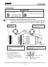
5.4 Wiring
5.4.1 Terminal Treatment of Cables
Follow the procedures below to treat the terminals (at the converter side) of various cables and install the
cables to the terminal block. Use appropriate cables based on the description in Section 5.1 "Cables." Crimp
a round type insulated crimp-type terminal to the end of the cables.
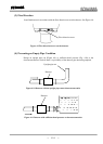
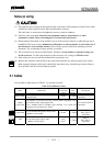
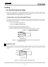
(1) Power cable, current output cable, digital I/O cables
The necessary cables should be ordered from the person responsible for the installation. Strip the sheath of
each conductor as shown in Figure 5.1 and attach a crimping terminal with insulated sleeve to it. The size of
the crimping terminal is as follows:
Integral type LF600F and LF610F: M4
Separate type LF602F and LF612F: M3.5
• Connect the power cable to terminal blocks L1 and L2.
• Connect the current output cable to terminal blocks + and -.
• Connect the digital I/O cable to terminal blocks D1, D01, D02 and COM, as required.
Figure 5.1 Terminal Treatment of Power Cable, Current Output Cable
and Digital I/O cable
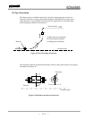
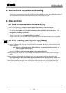
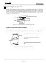
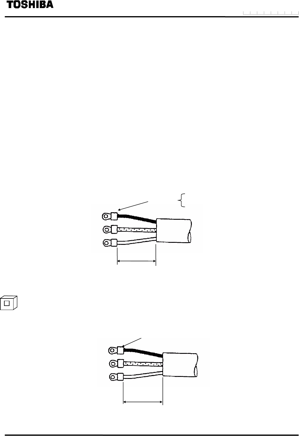
(2) Excitation cable
Strip the sheath from the end of each conductor as shown in Figure 5.2, attach an M3.5 crimping terminal
with insulated sleeve, and connect it to the terminal blocks X and Y. Connect the red conductor to terminal
block E.
Figure 5.2 Terminal Treatment of Excitation Cable
Crimping terminal
25~45mm
LF600F and LF610F type: M4
LF602F and LF612F type: M3.5
M3.5 crimping terminal
X Black
E Red
Y White
25~45mm
Separate