


- 30 -
6F8A0883
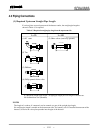
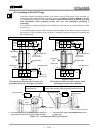
5.2 External Device Connections and Grounding
For the notes on connecting, wiring and installation of the combined converter, check the model number of
the combined converter and read the instruction manual of the relevant converter.
5.3 Notes on Wiring
5.3.1 Notes on Instrumentation-Converter Wiring
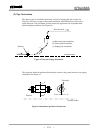
To avoid 2-point grounding, ground the shield of output cable basically at the receiving side.
Use a grounding wire of IV wire 5.5mm
2
or more. The size of the external grounding terminal screws is M4.
Do not share a grounding wire with other instruments where grounding current may flow. (An
independent grounding is preferable.)
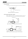
Power cable
When a 3-core cable is used: Ground with the FG terminal.
When a 2-core cable is used: Use an external grounding terminal and make the cable as short as possible.
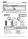
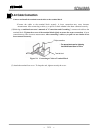
5.3.2 Notes on Wiring of the Separate type (GF632)
The detector is shipped with a flow rate signal cable and excitation cable. Be sure to use those cables coming
with the detector.
Note: When the cable length exceeds 300m, cables may not be supplied. Check whether the
cable is supplied with the specs.
The allowable cable length between the detector and converter varies depending on the conductivity of the
operating fluid. Refer to the instruction manual of the combined detector.
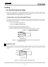
When connecting with the detector, wire the cables in the order of the excitation cable and flow rate signal
cable.
Because the input cables transmit very delicate signals, pass the excitation cable and input signal cable
separately through a thick steel conduit tube , keep them away from the large current wiring as far
as possible, and do not install them in parallel.
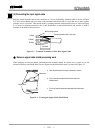
When replacing the flow rate signal cable and excitation cable, also refer to the instruction manual of the
relevant detector. Order the detector terminal box cover packing from Toshiba or a Toshiba distributor.
Separate