


Page 8
INSTALLATION MANUAL
REMOTE VEHICLE STARTER
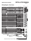
14 Pin Connector - Continued From Previous Page
1-Green Door Lock Door Lock Output - Programmable Menu 1 Setting 3.
2-Red 12vlt Output Output For Door Lock Module Only!
3-Blue Door Unlock Door Unlock Output - Programmable Menu 1 Setting 3.
4-Pink 2nd Unlock Output when Unlock button is press twice. May be
programmed as Auxiliary output on buttons #1 & #3
* The centre pin of the keyless entry harness is not to be used for anything besides
plug-in devices such as the VP-1, DL-3, DL-7 and Data Bus Modules. Overloading this
output will damage the remote starter.
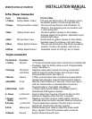
3 Pin Connector Red
4 Pin Connector Blue
2 Pin Connector White
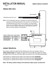
RF Antenna/ Program Button Connector.
Remove the plastic from the adhesive tape and place the antenna in the center of the
windshield, behind the rear view mirror. Run the cable behind the head liner and A-pillar
panels to the module under the dash.
****The Antenna Must Be Connected Before the System will Operate.****
Black (-) Horn Output for horn activation
Yellow (-) Park Lights Output for activation of negative park light systems. May
be programmed as Auxiliary output on button #2 & #3
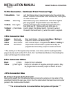
11-Blue/White Tach A/C Tach Signal Input. Used to detect when the vehicle has
started. This wire is connected to the vehicles coil, fuel injector
or crank sensor wire.
12-Blue Glow Plug Diesel Glow plug input, detects both 12volt and negative
glow plug signals. Programmable input. See Menu 3
13-White Park Lights +10amp park light output. At light harness 0volts when
Park lights are off, 12volts when park lights are on.
14-Black/ (-) Park Brake Input to detect Park Brake Switch. Connect to wire at
White the switch that switches to (-) when the switch is applied.