


C8051F04x-DK
Rev. 0.6 9
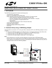
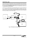
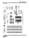
6.4. Serial Interface (J5)
A RS232 transceiver circuit and DB-9 (J5) connector are provided on the target board to facilitate serial connec-
tions to UART0 of the C8051F040. The TX, RX, RTS and CTS signals of UART0 may be connected to the DB-9
connector and transceiver by installing shorting blocks on headers J6, J8, J9 and J10.
J6 - Install shorting block to connect UART0 TX (P0.0) to transceiver.
J9 - Install shorting block to connect UART0 RX (P0.1) to transceiver.
J8 - Install shorting block to connect UART0 RTS (P4.0) to transceiver.
J10 - Install shorting block to connect UART0 CTS (P4.1) to transceiver.
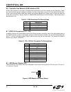
6.5. Analog I/O (J11, J20)
Several C8051F040 analog signals are routed to the J20 terminal block and the J11 header. The J11 connector
provides the ability to connect DAC0 and DAC1 outputs to several different analog inputs by installing a shorting
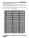
block between a DAC output and an analog input on adjacent pins of J11. Refer to Table 3 for J20 terminal block
connections and Table 4 for J11 pin definitions.
Table 3. J20 Terminal Block Pin Descriptions
Pin # Description
1HVAIN+
2HVAIN-
3 HVREF
4DAC1
5AIN0.0
6AIN0.1
7VREF0
8 ADND (Analog Ground)
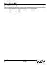
Table 4. J11 Connector Pin Descriptions
Pin # Description
1AIN0.0
2AIN0.1
3DAC0
4DAC1
5AIN0.2
6AIN0.3