


Precision - Page 31
6-Pin White Connector: Located on the front of the main module.
pin 1 VIOLET: Lock and unlock common input
pin 2 BROWN: Unlock Normally Closed
pin 3 BLUE: Unlock Output
pin 4 WHITE: Lock Normally Closed
pin 5 GREEN: Lock Output
pin 6 N.A
Plug-in Connectors
4-Pin White Connector: Dual stage shock sensor port* or optional 3 pulse negative start input (2200 Series)·
WHITE WIRE - 3 pulse remote start (-) input. Connect to the door lock output from the keyless entry system. When the
lock button is pressed 3 times the vehicle will start.
· BLUE WIRE - 1 pulse remote start (-) input. Connect to auxiliary output from aftermarket alarm.
· RED WIRE - not used.
· BLACK WIRE - not used.
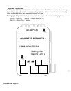
2-Pin Blue Connector: Valet switch port.Mount program switch in an area that is easily accessible from the driver’s
position.
2-Pin Red Connector: LED port. Mount LED in an area where it may be easily seen from either side of the vehicle.
5-Pin White Connector: Antenna connector
3-Pin Blue Connector: ScyNet Port connector
2-Pin White Connector: Temperature sensor Mount the temerature sensor either inside the Vehicle or in
engine compartment .
BLACK loop: located on the side of the main module, uncut= manual transmission, cut= Automatic
transmission.