


Precision - Page 29
System
Wiring
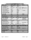
6-Pin Starter Harness
Pin 1 RED WIRE A: Main Power Input A (+). Connect to the battery or constant power wire at the ignition
switch with a minimum 25 Amp supply. Remove the fuse until the installation is complete and all wiring
is checked.
Pin 2 RED WIRE B: Main Power Input B (+). Connect to the battery or constant power wire at the ignition
switch with a minimum 25 Amp supply. Note: if connecting at the ignition switch it is highly
recommended to use separate power wires for each Red wire, each with a minimum 25A supply.
Remove the fuse until the installation is completed and all wiring is checked.
Pin 3 BROWN WIRE: Second Ignition Output (+). The Brown wire provides +12V for a second ignition
wire. This wire may instead be programmed for use as a second accessory or second starter wire.
Pin 4 ORANGE WIRE: Accessory Output (+). Connect to the accessory wire coming from the ignition
switch that supplies power to the heater/air-conditioner. Some cars may have multiple accessory wires.
Pin 5 YELLOW WIRE: Ignition Output (+). Connect to the main ignition wire that provides +12V when the
ignition is on and while cranking the starter.
Pin 6 VIOLET WIRE: Starter Output (+). Connect to the the vehicle’s starter wire.
16-Pin Main Harness
Pin 1 BROWN/WHITE WIRE: Horn Output (-) 500 mA. Connect to a relay to activate the vehicle’s horn
when the alarm is triggered. This wire may instead be programmed as an ignition 3 relay trigger.
Pin 2 BLUE/ORANGE WIRE: Ground When Running Output (-) 500 mA. Connect to an optional factory
security bypass module if required Or to a clutch switch bypass relay pin#86 for manual
Pin 3 GREEN/WHITE WIRE: Brake Input (+). Connect to the wire that shows +12V when pressing the
brake. The Green/white wire is a safety shutdown wire that must be connected.
Pin 4 BLACK/GRAY WIRE: Tach Input. Connect to the vehicle’s tach wire or a fuel injector wire if the
tachless mode does not provide satisfactory operation.
Pin 5 RED WIRE: Module Power Input (+). Connect to a constant source of +12V.
Pin 6 BLACK WIRE: Ground Input (-). The Black wire must connect to a solid chassis ground. Clean away
any paint or dirt to insure the best possible ground.
Pin 7 WHITE/VIOLET WIRE: Auxiliary 4 / Factory Rearm Output (-) 500 mA. White/violet wire
Auxiliary 4: Momentary output when channel is activated.
Factory Rearm Output: provides a ground output on remote start shutdown to rearm a factory security
system. Connect to the wire that requires a ground pulse to rearm the factory security system.
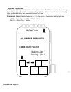
Pin 8 WHITE WIRE: Parking Light Output (+/-) relay. Connect the White wire to the circuit that shows
+12V or ground only when the parking lights are on and set the internal parking light relay jumper to
the proper polarity. For parking light circuits exceeding 10 amps, a relay is required. For vehicle’s with
independent left and right parking light circuits, diodes must be installed to keep the circuits separate.
NOTE: Do not connect the WHITE wire directly to the vehicle’s headlight circuit.
Pin 9 WHITE/BLACK WIRE: Hood/Trunk Pin Input (-). Connect the to the hood/trunk pin switch. The
switch must provide a ground output when switch is opened.
Pin 10 BLACK/WHITE WIRE: Dome Light Output (-) 500 mA. Connect to the wire that activates the
vehicle’s dome light, usually the door pin switch wire (see Green and Violet door trigger wires). Note:
MUST USE RELAY