


Precision Pro - Page 30Page 30 - Precision
Pin 11 BROWN WIRE: Siren Output (+) 3A. The Brown wire must connect to the siren’s red wire. The
Black siren wire must be grounded.
Pin 12 VIOLET WIRE: Positive Door Input (+). Connect to the door switch circuit wire that shows +12V
when the door is open. This type of door circuit is usually found on Ford
vehicles.
Pin 13 GREEN WIRE: Negative Door Input (-). Connect to the door switch circuit wire that shows ground
when the door is open.
Pin 14 WHITE/VIOLET WIRE: Factory Disarm Output (-) 500 mA. The Violet/white wire provides a
ground output on disarming and before remote starting to disarm a factory security system. Connect
to the wire that requires a ground pulse to disarm the factory security system.
Pin 15 ORANGE WIRE: Armed Output (-) 500 mA. The Orange wire provides a ground output while
armed to activate a relay for starter defeat and anti-grind protection or window rollup module.
Pin 16 WHITE/ORANGE WIRE: Parking Light 2 Output (+/-) relay. Connect the White wire to the circuit
that shows +12V or ground only when the parking lights are on and set the internal parking light
relay jumper to the proper polarity. For parking light circuits exceeding 10 amps, a relay is required.
For vehicle’s with independent left and right parking light circuits, diodes must be installed to keep
the circuits separate. NOTE: Do not connect the WHITE wire directly to the vehicle’s headlight circuit.
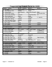
10-Pin Harness
Located on the front of the main module.
Pin 1 ORANGE/WHITE WIRE: Disarmed Output (-) 500 mA. The wire provides a ground output while
disarmed.
Pin 2 GRAY WIRE: Auxiliary 1 Output (-) 500 mA. Connect to a relay for an optional feature such as
trunk release, etc.
This output may be programmed for momentary, timed, or latched operation.*
Pin 3 BLACK/YELLOW WIRE: Auxiliary 3 Output (-) 500 mA. Connect to a relay or module for an
optional feature such as power window activation, etc. This output may be programmed for
momentary, timed, or latched operation.
Pin 4 WHITE/RED WIRE: Auxiliary 2 Output (-) 500 mA. Connect to a relay or module for an optional
feature such as power window activation, etc. This output may be programmed for momentary,
timed, or latched operation.
Pin 5 BLUE/WHITE WIRE: Passenger Unlock Output (-) 500 mA. Connect to a relay to unlock the
passenger doors when the system is configured for Driver Priority Unlocking.
Pin 6 BLUE/YELLOW WIRE: Glow Plug Input (+/-). For vehicles equipped with diesel engines the
Blue/yellow wire must be connected to the wait-to-start light in the gauge panel. This wire polarity
is programmable.
Pin 7 BLUE WIRE: Trunk Pin Input (-). Connect the to the trunk pin switch. The switch must provide a
ground output when switch is opened.
Pin 8 BLUE/WHITE WIRE: Sensor 2/Auxiliary Start Input (-). In Manual Trusmmission mode it is a
Turbo
Timer cancel input for systems in Turbo Timer mode. (this feature allows the the turbo timer feature to be
temporarilly canceled for remote start applications on manual transmission vehicles) A seperate push button
switch wired to GROUND is needed. To temporarily bypass the turbo timer in order to perform the remote start
procedure for manual transmissions:
Pin 9 GREEN/WHITE WIRE: Immergency Brake Input (-). For Manual Transmission and/or vehicles
equipped with a turbo charged engine. Must be connected if using the Turbo Timer feature and/or
Manual Transmission remote start feature..
Pin 10 YELLOW/RED WIRE: Oil Pressure Switch Input (+/-).