Page 12 - Galaxy 2000RS Plus
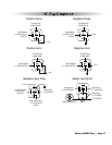
Pin 13 WHITE/BLACK WIRE: Hood Pin Input (-). Connect the to the hood pin switch. The switch must
provide a ground output when switch is opened.
Pin 14 ORANGE WIRE: Starter Interrupt Output (-) 500 mA. The wire provides a ground output when doors
are locked with remote control.
Pin 15 VIOLET/WHITE WIRE: Factory Disarm Output (-) 500 mA. The Violet/white wire provides a ground
output on disarming and before remote starting to disarm a factory security system. Connect to the
wire that requires a ground pulse to disarm the factory security system.
Pin 16 WHITE/VIOLET WIRE: Factory Rearm Output (-) 500 mA. The White/violet wire provides a ground
output on remote start shutdown to rearm a factory security system. Connect to the wire that requires
a ground pulse to rearm the factory security system.
Pin 17 BROWN WIRE: Audible Status Output (+) 3A. The Brown wire may be connected to an optional
audible status indicator such as a siren or piezo device.
Pin 18 GRAY WIRE: Auxiliary 1 Output (-) 500 mA. Connect to a relay for an optional feature such as trunk
release, etc. This output may be programmed for momentary, timed, or latched operation.
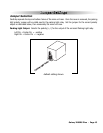
Pin 19 WHITE WIRE: Parking Light Output (+/-) relay. Connect the White wire to the circuit that shows
+12V or ground only when the parking lights are on and set the internal parking light relay jumper to
the proper polarity. For parking light circuits exceeding 10 amps, a relay is required. For vehicle’s with
independent left and right parking light circuits, diode must be installed to keep the circuits separate.
NOTE: Do not connect the WHITE wire to the vehicle’s headlight circuit.
Pin 20 BROWN/WHITE WIRE: Horn Output (-) 500 mA. Connect to a relay to honk the vehicle’s horn when
the panic feature is triggered. This wire may instead be programmed as an ignition 3 relay trigger.
Plug-in Connectors
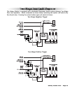
4-Pin White Connector: Auxiliary start input port for use with after-market security system.
· WHITE WIRE - 3 pulse remote start / Parking Brake (-) input.
3 Pulse R
emote Start Input:
Connect to the door lock output from the keyless entry system. When the
lock button is pressed 3 times the vehicle will start.
P
arking Brake Input: For vehicles equipped with a turbo charged engine, this wire must be connected to
the parking brake wire if using the optional Turbo Timer feature. For vehicles with a positive parking brake
wire, a relay must be used to invert the polarity.
· BLUE WIRE - 1 pulse remote start (-) input. Connect to auxiliary output from aftermarket alarm.
· RED WIRE - not used.
· BLACK WIRE - not used.
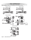
2-Pin Blue Connector: Valet switch port. Mount switch where it is accessible from the driver’s position.
2-Pin Red Connector: LED port. Mount LED where it may be easily seen from either side of the vehicle.
3-Pin White Door Lock Connector: Door lock port.
· BLUE WIRE - negative unlock output (-) 500mA.
· RED WIRE - (+) 100mA trigger output for optional plug-in door lock relay module,
· GREEN WIRE - negative lock output (-) 500mA.
3-Pin Blue Network Connector: The plug-in network connector port is located on the side of the main
module. This network port may be used with the optional personal computer interface or Pocket PC for
diagnostics, software customization and expanded programming options. The network also offers
connection to several optional accessories.
See your dealer for more information.
4-Pin White Flat Connector: Antenna connector port.


