


Contents Page
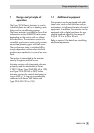
1 Design and principle of operation . . . . . . . . . . . . . . . . . . . 5
1.1 Additional equipment. . . . . . . . . . . . . . . . . . . . . . . . . . 5
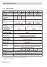
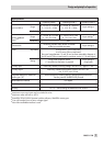
1.2 Technical data . . . . . . . . . . . . . . . . . . . . . . . . . . . . . 6
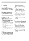
2 Installation. . . . . . . . . . . . . . . . . . . . . . . . . . . . . . . 8
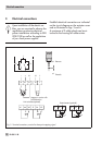
2.1 Mounting position . . . . . . . . . . . . . . . . . . . . . . . . . . . 8
2.2 Attachment to the valve . . . . . . . . . . . . . . . . . . . . . . . . . 8
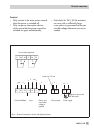
3 Electrical connections . . . . . . . . . . . . . . . . . . . . . . . . . 10
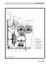
4 Operation and setting . . . . . . . . . . . . . . . . . . . . . . . . 12
4.1 Manual operation of the actuator . . . . . . . . . . . . . . . . . . . 12
4.2 Setting the additional equipment . . . . . . . . . . . . . . . . . . . . 12
4.2.1 Limit switches . . . . . . . . . . . . . . . . . . . . . . . . . . . . . 12
4.2.2 Potentiometers . . . . . . . . . . . . . . . . . . . . . . . . . . . . 12
4.3 Setting the digital positioner . . . . . . . . . . . . . . . . . . . . . . 14
5 Retrofitting additional electrical equipment . . . . . . . . . . . . . . 17
5.1 Limit switches . . . . . . . . . . . . . . . . . . . . . . . . . . . . . 18
5.2 Potentiometers . . . . . . . . . . . . . . . . . . . . . . . . . . . . 20
5.3 Digital positioner . . . . . . . . . . . . . . . . . . . . . . . . . . . 21
5.3.1 Calibrating the positioner . . . . . . . . . . . . . . . . . . . . . . . 22
5.3.2 Simplest method to calibrate the actuator. . . . . . . . . . . . . . . . 22
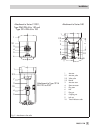
6 Dimensions in mm . . . . . . . . . . . . . . . . . . . . . . . . . . 23
2 EB 8331-1 EN
Contents