3 Electrical connections
Upon installation of the electric ca
-
bles, you are required to observe the
regulations concerning electrical
power installations according to DIN
VDE 0100 as well as the regulations
of your local power supplier.
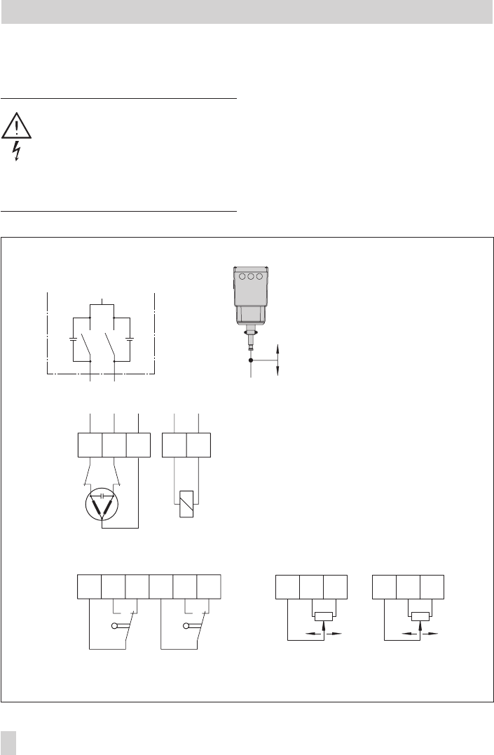
Establish electrical connections as indicated
on the circuit diagram on the actuator cover
and as illustrated in Figs. 3 and 4.
A maximum of 3 cable glands can be at
-
tached to the housing for cable entries.
10 EB 8331-1 EN
Electrical connections
aL eL N
NL
N+–LN
eL
aL
Ce
Ce
L
41 44 42 51 54 52
81 82 83 91 92 93
ea ae
Fig. 3 · Terminal connections, version for three-point stepping signal
Magnet in version with
fail-safe action
Limit switches (optional)
Retracts
Extends
Potentiometer (optional)


