10.7
ELECTRICAL
10
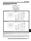
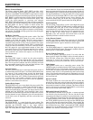
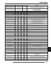
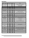
CONNECTOR 1 - PIN # SIGNAL NAME DESCRIPTION - IPS = Intelligent Power Switch
J1-A ACC_PWR IPS that provides power to the accessories
J1-B Unused
J1-C TRANS Input signal from the transmission
J1-D IDLE Input signal for Active Descent Control (ADC)
J1-E (X2 Only) TURF_MODE
High side enable to control differential solenoid. Uses SPEED and
TRANS signals to determine differential solenoid operation (X2 Only)
J1-F FAN_ON Relay input to control operation of the fan
J1-G KAP_EFI Relay input to control operation of the ECM relay
J1-H BAT+ Battery Positive
J1-J (X2 Only) DIFF_SOL+ IPS that provides power to the differential solenoid
J1-K FAN IPS that operates the fan
J1-L (X2 Only) DIFF_SOL- Low side connection to the differential solenoid
J1-M ADC IPS that activates ADC hub coil
J1-N GND Battery Ground
J1-P Unused
J1-R Unused
J1-S ECM_RELAY IPS to the power the ECM relay output
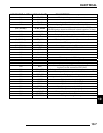
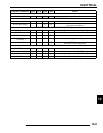
CONNECTOR 2 - PIN # SIGNAL NAME DESCRIPTION - IPS = Intelligent Power Switch
J2-A COIL 1 Input from stator coil winding 1 - 15k resistance to ground
J2-B RUN
Run input signal. Battery voltage when
key/run is on and connected to BAT_PROT
J2-C ECM_MEM Used to provide the instrument cluster constant power for memory
J2-D FAN_STAT Open collector output. Pulsed low upon overload or disconnect of FAN
J2-E FUEL_EN Fuel pump control input
J2-F BRAKE Input from brake switch. Enables starter interlock when high
J2-G LIGHTS High side drive for vehicle lights
J2-H COIL 2 Input from stator coil winding 2
J2-J COIL 3 Input from stator coil winding 3
J2-K SPEED Input from speed sensor for ADC operation
J2-L FUEL_PUMP IPS to power the fuel pump output
J2-M BAT_PROT Protected battery output to general vehicle loads
J2-N STARTER Low side starter solenoid connection.
J2-P IGNITION IPS to power the ignition output.


