


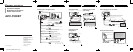
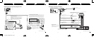
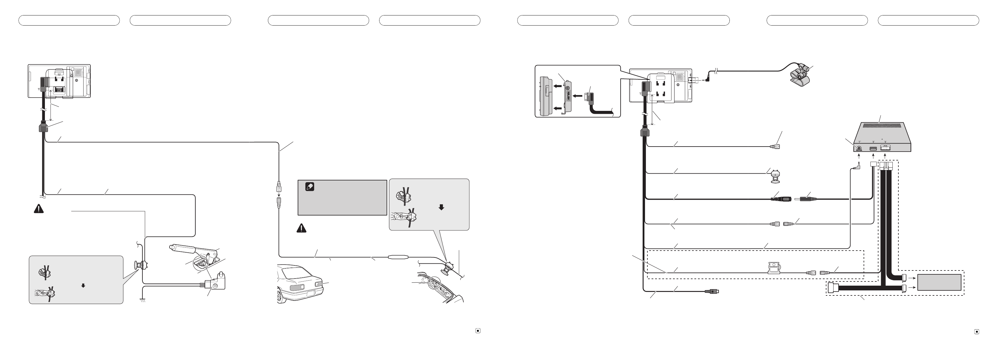
Connecting the reverse signal and parking brake leads
2 m (6 ft. 7 in.)
20 cm (7-7/8 in.)
2 m (6 ft. 7 in.)
3. PARKING BRAKE (Light green)
Used to detect the ON/OFF status of the parking brake. This lead
must be connected to the power supply side of the parking
brake switch.
If this connection is made incorrectly or omitted, certain
functions of your navigation system will be unusable.
LIGHT GREEN LEAD AT POWER CONNECTOR IS
DESIGNED TO DETECT PARKED STATUS AND
MUST BE CONNECTED TO THE POWER SUPPLY
SIDE OF THE PARKING BRAKE SWITCH.
IMPROPER CONNECTION OR USE OF THIS LEAD
MAY VIOLATE APPLICABLE LAW AND MAY
RESULT IN SERIOUS INJURY OR DAMAGE.
WARNING
5. Connection method
6. Clamp the parking brake
switch power supply side
lead.
7. Clamp firmly with needle-
nosed pliers.
8. Power supply side
9. Ground side
10. Parking brake switch
1. This product
2. Cable (supplied)
4.
English
En
11. REVERSE-GEAR SIGNAL INPUT (Violet/white)
This is connected so that the navigation system can detect whether the vehicle is
moving forwards or backwards. Connect the violet/white lead to the lead whose
voltage changes when the shift lever is put in reverse. Unless connected, the
sensor may not detect your vehicle traveling forward/backward properly, and thus
the position of your vehicle detected by the sensor may be misaligned from the
actual position.
14. Clamp the backup
light lead.
Be sure to use only the supplied extension lead. Use of
another lead could cause fire, smoke and/or damage this
navigation system.
CAUTION
20. Check the position of your vehicle’s
backup light (the one that lights up
when the shift lever is in reverse
[R]) and find the backup light lead
in the trunk.
17. Extension lead
(for reverse signal)
5 m (16 ft. 5 in.)
18. Fuse resistor
19. Backup
light lead
12.
13. Connection method
15. Clamp firmly with
needle-nosed pliers.
16.
Note
When you use a rear view camera,
please make sure to connect this
lead. Otherwise you cannot switch to
rear view camera picture.
Fig. 7 Abb. 7 Afb. 7 Рис.7
En
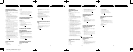
Connecting to a separately sold amplifier
50 cm (1 ft. 8 in.)
2 m (6 ft. 7 in.)
1.5 m (4 ft. 11 in.)
20 cm (7-7/8 in.)
20 cm (7-7/8 in.)
2 m (6 ft. 7 in.)
1. Cradle
3. This product
2. Cable (supplied)
5. R
E
(R
e
pa
r
8. P
A
(
R
p
a
11. AMP CONTROL (Blue/white)
15.
F
(
19. Rear view camera input (Brown)
(Refer to When connecting a rear view camera.)
1.5 m (4 ft. 11 in.)
50 cm (1 ft. 8 in.)
14. Battery cable (Yellow)
This terminal is on the North American
model only.
Be sure to connect this lead to terminal
always supplied with power regardless
of ignition switch position.
17. T
h
n
A
En
20. For details, refer to the owner's manual supplied with ND-G500.
4. Microphone
(CD-VM1) (sold separately)
5. REVERSE-GEAR SIGNAL INPUT (Violet/white)
(Refer to Connecting the reverse signal and
parking brake leads.)
8. PARKING BRAKE (Light green)
(Refer to Connecting the reverse signal and
parking brake leads.)
6. ND-G500 (sold separately)
7. To AUDIO IN
9. Black 10. DC 5V (Black)
12. Blue/white
13. Audio output (Left, Right) (Black)
15. Fuse holder
(Fuse: 1 A)
18. Factory radio
16. Yellow
17. This connection is
necessary for the North
American model only.
Fig. 8 Abb. 8 Afb. 8 Рис.8
En
<F500BT_CONNECTION> -Page 5