6-2
P/N: 4809641a
©2006 Paxton Automotive
All Rights Reserved, Intl. Copr. Secured
01MAY06 v1.1 Dodge Ram 1500(4809641a v1.1)
*** NOTE ***
On some models, this step may differ from the photo and
procedure shown here.
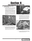
J Locate the crank case breather hose that was
originally attached to the factory air filter
assembly. Towards the back of the engine,
there is a tube that runs across from the dri-
ver’s side to the passenger’s side. On the
driver’s side, there is a TEE coupler. This
was originally connected to the factory air
box.
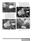
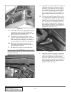
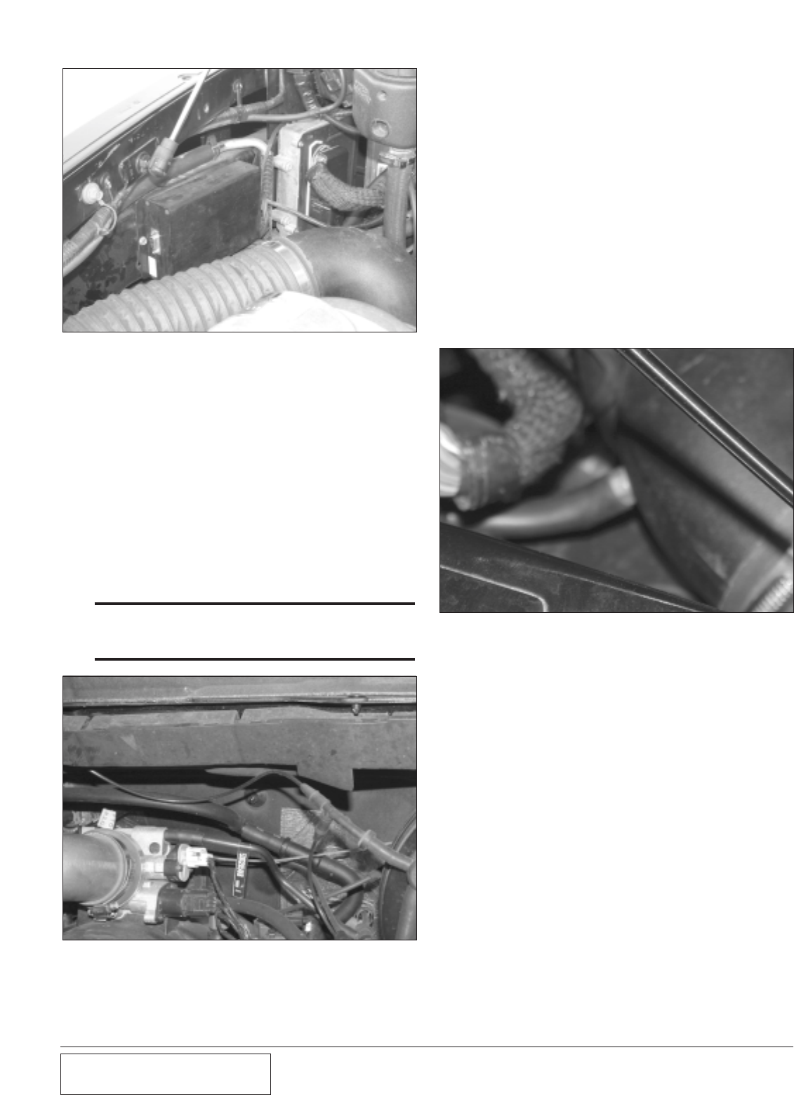
K. Connect the supplied length of hose to the
1/2" nipple that is installed in the air intake
assembly, and it would be located on most
vehicles next to the compressor bypass fit-
ting. This fitting is not installed. You will
have to drill and tape the hole. Because of
the variations in vehicles, you will have to
find a suitable location for your particular
application. (See Fig. 6.1-f.)
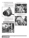
Fig. 6.1-e
Fig. 6.1-f
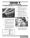
L. Install the air intake assembly. Connect the
compressor bypass to the larger hose barb
and secure. Attach the air filter housing
using the supplied sheet metal screws to the
frame rail next to the radiator. Install the air
filter assembly and attach with the screws
supplied. (See Fig. 6.1-g.)
E. Attach the red wire from the supplied engine
management unit to the #87 on the relay.
Again using drawing number 1017718, find
the black plug on the factory ECU.
G. Locate the pin numbers and splice in the
supplied engine management unit. There are
eight supplied butt connectors. Although
with care, the butt connectors will work. We
recommend that you solder the connections.
H. Route the injector harness across to the
supercharger discharge tube and connect to
the supplemental injector.
I. Re-install the coolant overflow and hoses.
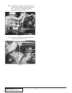
Fig. 6.1-d


