


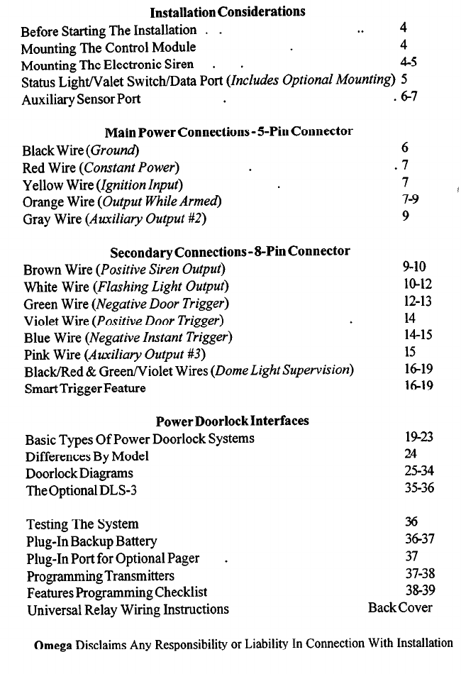
Installation Considerations
Before Starting The Installation . .
. . 4
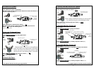
Mounting The Control Module
4
Mounting The Electronic Siren .
.
4-5
Status Light/Valet Switch/Data Port (Includes Optional Mounting) 5
Auxiliary Sensor Port
.67
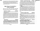
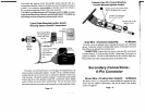
Main Power Connections - 5-Pin Connector
Black Wire (Ground)
Red Wire (Constant Power)
Yellow Wire (Ignition Input)
Orange Wire (Output While Armed)
Gray Wire (Auxiliary Output #2)
Secondary Connections-8-Pin Connector
Brown Wire (Positive Siren Output)
White Wire (Flashing Light Output)
Green Wire (Negative Door Trigger)
Violet Wire (Positive Door Trigger)
Blue Wire (Negative Instant Trigger)
Pink Wiie (Auxiliary Output #3)
Black/Red & Green/Violet Wires (Dome Light Supervision)
Smart Trigger Feature
PowerDoorlockInterfaces
Basic Types Of Power Doorlock Systems
Differences By Model
Doorlock Diagrams
The Optional DLS3
Testing The System
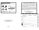
Plug-In Backup Battery
Plug-In Port for Optional Pager .
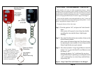
Programming Transmitters
Features Programming Checklist
Universal Relay Wiring Instructions
6
.7
7
7-9
1
9
9-10
lo-12
12-13
14
14-15
15
16-19
16-19
19-23
24
25-34
35-36
36
3637
37
37-38
3&39
BackCover
Omega
Disclaims Any Responsibility or Liability In Connection With Installation