


25
Enter Backdoor mode by typing: !11,MW,1000,1[CR]
Unit will respond with: !11,BackDoorEnabled: Y
Disable DAC update by typing: !11,WRITE,4,D[CR]
Unit will respond with: !11,DisableUpdate: D
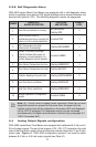
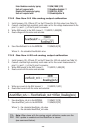
7.3.2 Gas flow 0-5 Vdc analog output calibration
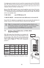
1. Install jumpers J7A, J7B and J7C on the PC board for 0-5 Vdc output (see Table VI).
2. Connect a certified high sensitivity multi meter set for the voltage measurement to the
pins 2 (+) and 1 (-) of the 15 pins D connector.
3. Write 4000 counts to the DAC channel 1: !11,WRITE,1,4000[CR]
4. Read voltage with the meter and calculate:
5. Save FlowOutScaleV in to the EEPROM: !11,MW,25,X[CR]
Where: X – the calculated AoutScaleV value.
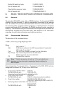
7.3.3 Gas flow 4-20 mA analog output calibration
1. Install jumpers J7A, J7B and J7C on the PC board for 4-20 mA output (see Table VI).
2. Connect a certified high sensitivity multi meter set for the current measurement to
pins 2 (+) and 1 (-) of the 15 pins D connector.
3. Write 4000 counts to the DAC channel 1: !11,WRITE,1,4000[CR]
4. Read current with the meter and calculate:
5. Write zero counts to the DAC channel 1: !11,WRITE,1,0CR]
6. Read offset current with the meter and calculate:
7. Save AoutScale_mA in to the EEPROM: !11,MW,27,Y[CR]
Save AoutOffset_mA in to the EEPROM: !11,MW,28,Z[CR]
Where: Y – the calculated AoutScale_mA value.
Z – the calculated AoutOffset_mA value.
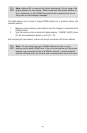
Note: When done with the analog output calibration make sure the
DAC update is enabled and the BackDoor is closed
(see command below).