


21
7.2 Gas Flow Calibration of FMA 4000 Mass Flow Meter
FMA 4000 Mass Flow Meters may be field recalibrated/checked for the same
range they were originally factory calibrated for. When linearity adjustment is
needed or flow range changes are being made, proceed to step 7.2.3. Flow range
changes may require a different Restrictor Flow Element (RFE). Consult Omega
®
for more information.
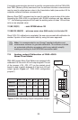
7.2.1 Connections and Initial Warm Up
Power up the Mass Flow Meter for at least 15 minutes prior to commencing the
calibration procedure. Establish digital RS485 / RS232 communication between
PC (communication terminal) and the FMA 4000. Start Omega
®
supplied calibra-
tion and maintenance software on the PC.
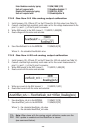
7.2.2 ZERO Check/Adjustment
Using Omega
®
supplied calibration and maintenance software open Back Door
access:
Query/BackDoor/Open
When software prompts with Warning, click the [YES] button. This will open the
access to the rest of the Query menu.
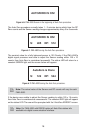
Start Sensor Compensated Average reading:
Query/Read/ SensorCompAverage
This will display Device Sensor Average ADC counts.
With no flow conditions, the sensor Average reading must be in the range 120±
10 counts. If it is not, perform Auto Zero procedure (see section 5.3.10 “Zero
Calibration”).
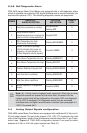
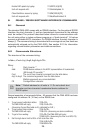
7.2.3 Gas Linearization Table Adjustment
All adjustments in this section are made from the outside of the meter
via digital communication interface between a PC (terminal) and FMA
4000. There is no need to disassemble any part of the instrument or
perform internal PCB component (potentiometers) adjustment.
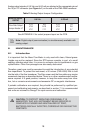
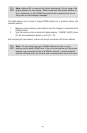
Note: Your FMA 4000 Digital Mass Flow Meter was calibrated at the
factory for the specified gas and full scale flow range (see device’s
front label). There is no need to adjust the gas linearization table
unless linearity adjustment is needed, flow range has to be changed,
or new additional calibration is required. Any alteration of the gas
linearization table will VOID calibration warranty supplied with instrument.