


17
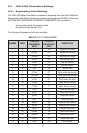
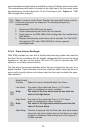
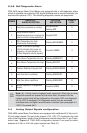
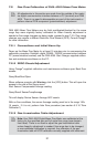
5.3.8 Self Diagnostic Alarm
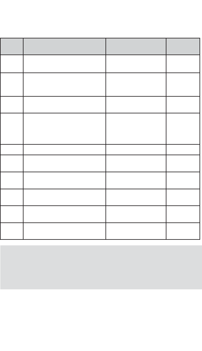
FMA 4000 series Mass Flow Meters are equipped with a self-diagnostic alarm
which is available via multicolor LED, digital interface and on screen indication (for
devices with optional LCD). The following diagnostic events are supported:
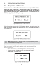
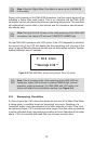
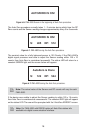
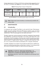
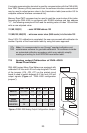
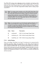
5.4 Analog Output Signals configuration
FMA 4000 series Mass Flow Meters are equipped with calibrated 0-5 Vdc and 4-
20 mA output signals. The set of the jumpers (J7A, J7B, J7C) located on the right
side of the flow meter, inside of the maintenance window above the 15 pin D-con-
nector (see Figure c-1 “FMA 4000 configuration jumpers”) are used to switch
between 0-5 Vdc or 4-20 mA output signals (see Table VI).
NUMBER
DIAGNOSTIC
ALARM DESCRIPTION
LED COLOR
AND PATTERN
PRIORITY
LEVEL
1
Auto Zero procedure is running
Not periodically
flashing RED
0
2
FATAL ERROR (reset or
maintenance service is required for
return in to the normal operation)
Constant RED 1
3
CPU Temperature too high
(Electronics Overheating)
Flashing RED/UMBER 2
4
Sensor in the warm up stage
(first 6 minutes after power up
sequence, normal operation, no
critical diagnostic events present)
Constant UMBER 3
5
Flow Sensor Temperature too low Flashing UMBER/OFF 4
6
Flow Sensor Temperature too high Flashing RED/OFF 5
7
Totalizer Reading hit preset limit Flashing GREEN/UMBER 6
8
Low flow Alarm conditions Flashing GREEN/OFF 7
9
High flow Alarm conditions Flashing GREEN/RED 8
10
Normal operation, no diagnostic
events
Constant GREEN 9
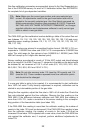
Note: [0] - Priority Level is highest (most important). When two or more
diagnostic events are present at the same time, the event with the
highest priority level will be indicated on the status LED and displayed
on the LCD (if equipped). All diagnostic events may be accessed
simultaneously via digital communication interface (see paragraph 8.3
“ASCII Command Set”).