


If a simple communication terminal is used for communication with the FMA 4000,
then “MW” (Memory Write) command from the software interface commands set
may be used to adjust sensor value in the linearization table (see section 8.3 for
complete software interface commands list).
Memory Read “MR” command can be used to read the current value of the index.
Assuming the FMA 4000 is configured with RS485 interface and has address
“11”, the following example will first read the existing value of Index 133 and then
write a new adjusted value:
!11,MR,133[CR] - reads EEPROM address 133
!11,MW,133,3450[CR] - writes new sensor value (3450 counts) in to the index 133
Once 100% F.S. calibration is completed, the user can proceed with calibration for
another 9 points of the linearization table by using the same approach.
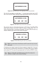
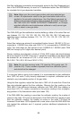
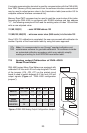
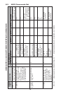
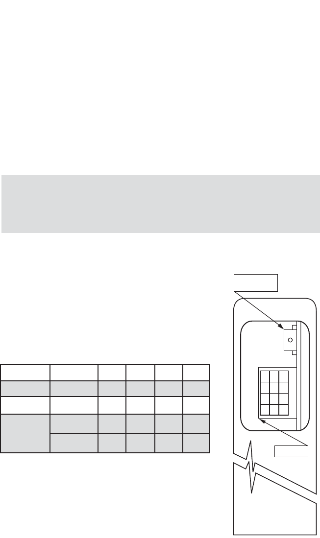
7.3 Analog output Calibration of FMA 4000
Mass Flow Meter
FMA 4000 series Mass Flow Meters are equipped with
calibrated 0-5 Vdc and 4-20 mA output signals. The set
of the jumpers (J7A, J7B, J7C) on the printed circuit
board is used to switch between 0-5 Vdc and 4-20 mA
output signals (Figure c-1 “FMA 4000 configuration
jumpers”).
Figure c-1 FMA 4000 Analog Output Configuration Jumpers
23
Note: It is recommended to use Omega
®
supplied calibration and
maintenance software for gas table calibration. This software includes
an automated calibration procedure which may radically simplify
reading and writing for the EEPROM linearization table.
FUNCTION J7A
J7B J7C
JCD
ANALOG 0-5 VDC 5-9 6-10 7-11
OUTPUT 4-20 mA 1-5 2-6 3-7
RS485
TERMINAL
RESISTOR
OFF
8-12
ON 4-8
AutoZero/Reset
push button.
J7 Jumpers
9
10
11
12
5
6
7
8
1
2
3
4
A
B
CD