


1-3
3. TRANSDUCER/POWER CONNECTIONS
A. Do not
attempt to add additional cable to the
transducers.
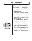
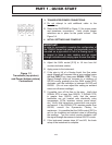
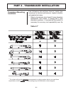
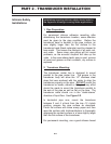
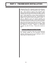
B. Refer to the DIAGRAMS in Figure 1.2 for proper power
and transducer connections. Verify proper jumper
selections are in place for the power source. See
Figure 3.4.
4. INITIAL SETTINGS AND POWER UP
A. Adjust the GAIN control [R13] to 1/4 turn from full
counter-clockwise rotation.
B. Apply power to the instrument.
C. If the pipe is full of a flowing liquid, the flow meter
signal strength will increase from a zero reading.(press
the
2nd FUNCT
key, then press
SIGNAL STR)
. If the
Signal Strength does not increase to a minimum of
000125 counts, gradually turn the GAIN control [R13]
clockwise until the indication is between 000125 and
000200. (Do not over adjust this setting as ambient
noise can influence readings.)
D. If possible, turn off the flow in the pipe. Verify that
SIGNAL STR. is lower than 000100. If SIGNAL STR.
is greater than 000100, verify that the sensor/
transmitter are not located near electrically noisy
components. (VFDs, inverters, motors, power relays,
etc) Verify that transducer connections are proper
and secure. If the SIGNAL STR. remains greater than
000100, consult the Dynasonics Factory for
assistance. It is possible that the GAIN control [R13] is
set too far clockwise and ambient noise is influencing
the readings. Turn the control counter-clockwise until
the signal strength decreases to below 000070 counts.
E. If the instrument passes steps 4C and 4D, the basic
setup of the instrument is complete.
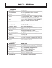
PART 1 - QUICK START
IMPORTANT!
In order to successfully complete the configuration of
the FD6000 Series flow meter, the transducer must be
mounted on a pipe which is full of a flowing liquid. It
is normal to have a zero reading and no signal
strength indication with empty pipes or zero flow rate.
Figure 1.2
Transducer (top picture)
and Power (bottom picture)
Connections