


2-2
operating range of the meter. Down stream from
pump or orifices, etc., locate at least 20 diameters.
See
Table 2.1
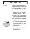
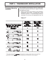
2. On horizontal pipe, select a position that is
between 2 and 4 o’clock on the pipe, with 12
o’clock representing the top. If the transducer is
to be mounted on a vertical pipe, select a section
of pipe where the flow is moving from bottom to
top (flow moving vertically down a pipe tends to
cavitate and provide unreliable operation.)
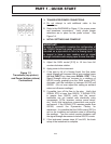
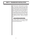
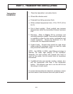
3. Mount the transducer in the orientation shown in
Figure 2.2. The flow meter will read flow in both
directions, but will be most accurate if the cable is
mounted in the orientation shown—pointing in the
primary flow direction.
4. If totalization of the measured fluid is required, the
pipe must remain full. The meter will read when
the liquid level is greater than the placement of the
transducer, but the volumetric measurement will
be based on a full pipe, so totalization will be
higher than actual.
5. The flowmeter will achieve proper Doppler signals
off of turbulence; however, it should be noted that
turbulence may not be linear with pump speed
changes, nor is the reading necessarily accurate
due to the non-uniformity of turbulence.
6. When a liquid has less than 100 PPM of 100
micron or larger particles, try mounting the
transducer within 12 inches of a pump discharge
or other source of flow turbulence or cavitation. A
reading obtained under these circumstances will
be repeatable, but not necessarily accurate or
linear.
7. It is a good practice to test the flow meter on the
piping system before permanently mounting the
transducer using RTV. Function can be verified
by applying a water soluble lubricant, such as KY-
Jelly, and holding the transducer by hand on the
pipe in the location where the transducer will be
PART 2 - TRANSDUCER INSTALLATION
FLOW
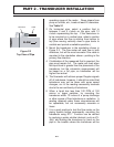
Figure 2.2
Top View of Pipe
Transducer Cable