


3-6
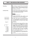
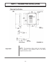
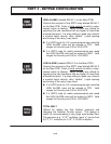
1. Guide the transducer terminations through the
transmitter conduit hole located on the left side of the
enclosure. Secure the transducer cable with the
supplied conduit nut.
2. The terminals on the transducer cable are coded with
wire markings. Connect the appropriate wires to the
corresponding screw terminals in the transmitter.
NOTE: The transducer cable carries low level signals.
Do not attempt to add additional cable to the factory
supplied transducer cable.
If additional cable is required contact OMEGA Engineering
to order a transducer with the appropriate length of cable
Cables to 300 feet [90 meters] are available.
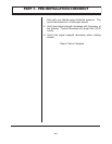
NOTE: An additional hole in the transmitter enclosure is
required for outputs. Drill the hole in the the enclosure
bottom taking care not to drive the drill bit into wiring or the
circuit boards with the transmitter.
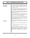
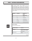
The CTR pulse output is proportional to the flow rate
measuring scale. This output may be used one of two
ways:
♦
To drive a 12V logic device or electromechanical total-
izers.
♦
To drive a low impedance, 12V device. Minimum
resistance 50 ohms.
The pulse output pulses with totalizer increments. The
connections are located on the right side of the signal
processing PCB in the back of the enclosure. The pulse
width is fixed at 50 milli-seconds. CTR “ - ” represents
circuit low. CTR “ + “ represents 12 Vdc pulse output.
PART 3 - TRANSMITTER INSTALLATION
CTR Output
Transducer
Connections