


3-1
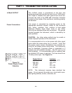
PART 3 - PRE-INSTALLATION CHECKOUT
After unpacking, it is recommended to save the shipping
carton and packing materials in case the instrument is
stored or re-shipped. Inspect the equipment and carton
for damage. If there is evidence of shipping damage,
notify the carrier immediately.
The FD6000 Series flowmeter can be checked for basic
functionality using the following Bench Test procedure.
It is recommended that this operation be performed
before permanently installing the system.
Procedure:
1. Open the transmitter cover.
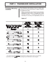
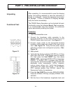
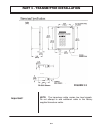
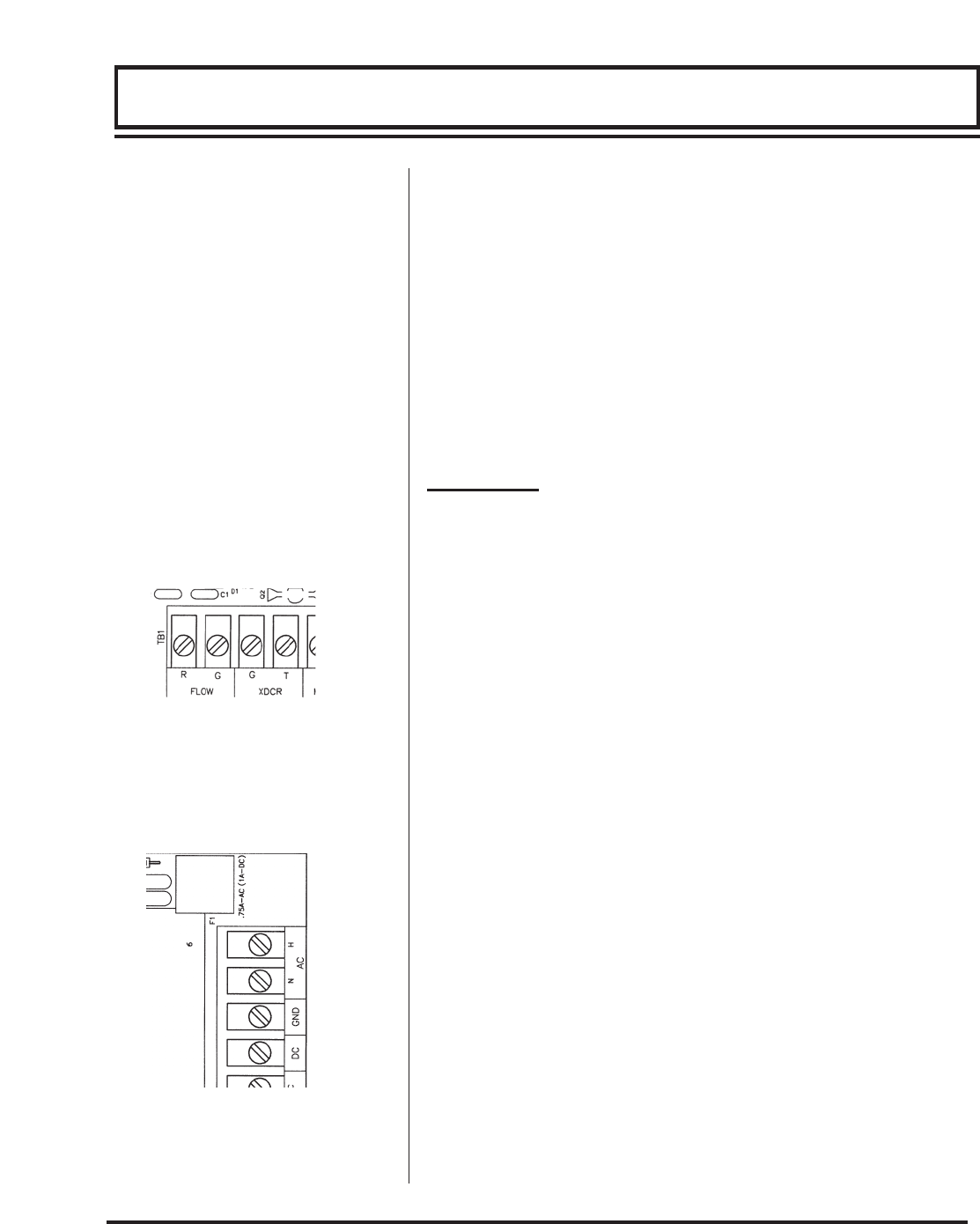
2. Connect the transducer cable connector to the
terminal locations on the lower left corner of the
FD6000 Series main circuit card. See Figure 3.1.
3. Connect supply power to the appropriate terminal
locations on the upper right corner of the main circuit
card. See Figure 3.2. Verify that the power supply
selection jumpers are configured properly—See
Figure 3.4.
4. Apply power.
5. Verify that the display indicates 0.00 FPS (or 0.0 flow
rate of any other unit). If the display does not register
0.0, then press the 2nd FUNCT key, then press
SIGNAL STR. Verify that SIGNAL STR. is lower than
000100. If SIGNAL STR. is greater than 000100,
verify that the sensor/transmitter are not located near
electrically noisy components. (VFDs, inverters,
motors, power relays, etc) Verify that transducer
connections are proper and secure. If the SIGNAL
STR. remains greater than 000100, consult the
Dynasonics Factory for assistance.
6. Press the 2nd FUNCT key to enter SERVICE MODE.
Press the SIGNAL STR key to display SIGNAL STR.
XXXXXX.
7. Rub the face of the transducer lengthwise back and
Unpacking
Functional Test
Figure 3.2
Figure 3.1