


3-5
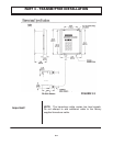
The 4-20mA output is proportional to the flow rate
measuring scale and can drive a load of up to 1000 ohms.
The output is isolated from earth ground and circuit low.
Connect the load to the 4-20 mA connection terminals
located on the inside of the enclosure, matching polarity
as indicated.
Line power is connected by supplying power to the
appropriate terminals located inside of the enclosure
Use wiring practices that conform to local codes
(National Electric Code Hand book in the USA).
Use only the standard three wire connection. The ground
terminal grounds the instrument, which is mandatory for
safe operation.
CAUTION: Any other wiring method may be unsafe or
cause improper operation of the instrument.
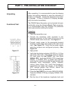
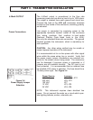
It is recommended not to run line power with other signal
wires within the same wiring tray or conduit. Verify that
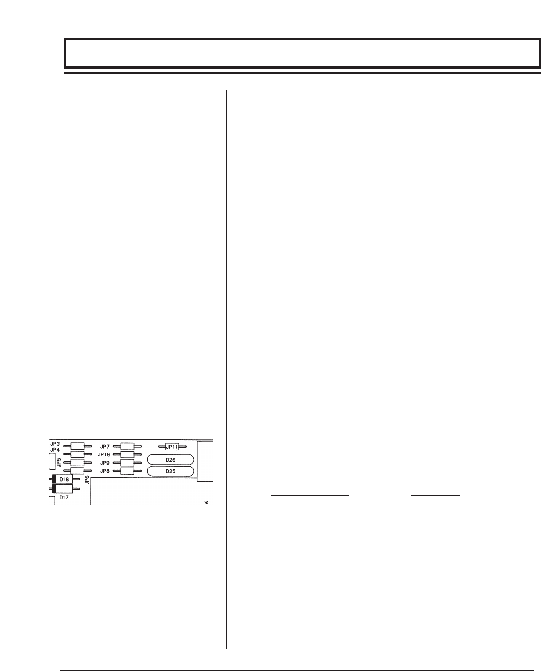
the power supply jumper connections are oriented cor-
rectly for the power source being wired. The electronics
can be damaged if improper power is connected or if
jumpers are not installed correctly. The DC input is not
fuse protected. It is recommended that an external fuse
be installed if DC power is selected. The fuse should be a
1A delay action type. See Figure 3.4
Power Source
Jumpers
115 VAC JP8, JP10, JP11
230 VAC JP9, JP11
100 VAC JP7
12 VDC JP3, JP5
24 VDC JP4, JP6
NOTE: This instrument requires clean electrical line
power. Do not connect the meter on a circuit which oper-
ates lighting ballasts, motors, solenoids, etc.
PART 2 - SERVICE AND MAINTENANCE
PART 3 - TRANSMITTER INSTALLATION
4-20mA OUTPUT
Power Connections
Figure 3.4
Power Supply Jumper
Selection