


15
3.6 ELECTRICAL CONNECTION
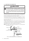
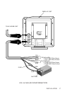
3.6.1 DC POWER CABLE
The RADAR 1500 MK2 will work with any electrical supply within the 10.2
to 16 V range, since it contains a power regulator circuit. Connect the power
cable to a DC source capable of supplying at least 3.5 A. The power cable
should normally be wired through a circuit breaker. The red lead wire of the
power cable must be connected to the positive source terminal and the black
lead to the source negative terminal. The shielded wire is be connected to Boat
Main ground. Should the power connections be inadvertently reversed, a pro-
tective fuse will blow. In this event, check the input power leads for correct
polarity with a VOM and reconnect the leads in their correct polarity. Replace
the fuse. The fuse is located in the power cable. [NORMAL-BROW FUSE (5
A) SHOULD BE SPECIFIED]
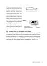
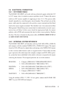
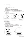
3.6.2 EXTERNAL SYSTEM INTERFACE
The RADAR 1500 MK2 will interface with any NAV-AID (GPS or LORAN)
and compass with the standard NMEA0182 or NMEA0183 output. The inputs
from the NAV-AID must be digital data conforming to the NMEA0183 formats
to drive various radar features such as waypoint mode. If more than one data
type is present at the radar input (for example; compass and NAV-AID) a prior-
ity system has been established in the radar’s software to respond to the inputs
in driving the features. The assigned priorities are set in this manner:
HEADING: 1. Compass (NMEA0183 “HDG,HDM,HDT,VHW”)
2. NAV-AID (NMEA0183 “RMC,RMA,VTG”)
POSITION: 1. NAV-AID (NMEA0l83 “RMC,RMA,GLL,GTD”)
SPEED: 1. NAV-AID (NMEA0183 “RMC,RMA,VTG”)
2. Compass (NMEA0183 “VHW”)
WAYPOINT: 1. NAV-AID (NMEA0183 “RMB,BWC”)
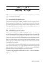
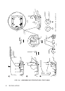
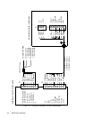
Using the outline of FIG. 3-7, FIG. 3-8 as a guide, connect the RADAR 1500
MK2 to your NAV-AID and compass.
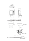
INSTALLATION