


12
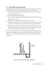
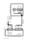
3.4 MOUNTING THE SCANNER UNIT
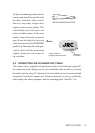
Selecting an adequate location for the scanner unit requires careful consider-
ation. On many small vessels, the unit can be installed on a mast platform, on
an arch or on a bridge structure near the ship’s center line.
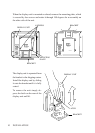
The radiator beam should not be obstructed by nearby large objects. Locate the
unit where large structures such as superstructures, searchlights, horns or masts
are not in the same horizontal plane, otherwise blind areas and false targets will
appear on the radar screen.
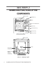
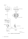
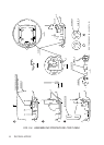
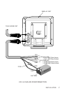
Using the outline drawing of FIG. 3-4 or the template in the front of the manual
as a guide, install the scanner unit by securing it to a solid mounting surface.
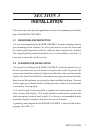
The attachment bolts are stainless steel hexhead bolts M6, 31.75 mm (1.25”)
long. Both flat and lock washers should be used. (See FIG. 3-5)
Note: Do not apply excessive torque to fix the bolts. Use a 11 cm-long wrench
(Fixing torque: 87 kgf-cm).
INSTALLATION
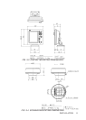
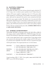
FIG. 3-5 MOUNTING BOLTS for SCANNER UNIT
Chassis
28 mm (1.4 inch)
3-15 mm (0.12-0.6 inch)
Thickness
Radome base
Mounting base
Stainless steel bolt
L=31.75 (1.25 inch)
5/16-18 UNC
(attached)
Plain washer
Lock washer
The scanner unit requires a minimum mounting surface thick-
ness of 3 mm (0.12 inches). If the thickness of the mounting base
is less than this, additional flat washers are required. If the thick-
ness is more than 15 mm (0.6 inches), longer hexhead bolts are
required.
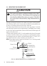
CAUTION