


7
SECTION 3
This section provides practical guidelines to assist in the planning and installa-
tion of the RADAR 1500 MK2.
3.1 UNPACKING AND INSPECTION
Use care when unpacking the RADAR 1500 MK2 from the shipping carton to
prevent damage to the contents. It is also good practice to save the carton and
the interior packing material until the radar has been satisfactorily installed.
The original packing material should be used in the unlikely event that it is
necessary to return the unit for service.
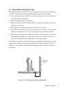
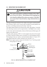
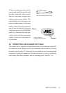
3.2 PLANNING THE INSTALLATION
The layout for installing the RADAR 1500 MK2 should be planned to give
the best operation and service aboard your particular vessel. In general, the
scanner unit should be mounted as high as possible above the waterline and the
display unit should be installed in a convenient viewing position near the helm.
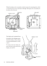
Keep in mind the optimum viewing angle when installing the display. You may
wish to apply power before finally installing the unit so that you can determine
a satisfactory viewing angle.
A 15 meter length of interunit cable is supplied for connecting the two main
units (scanner and display). This length should be sufficient to complete the
cable run required on most small vessels. It is, however, recommended that the
maximum length of interunit cable does not exceed 20 meters.
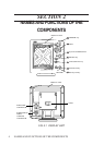
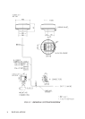
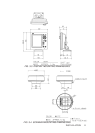
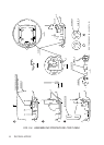
A general system diagram for the RADAR 1500 MK2 is shown on the follow-
ing page. (See FIG. 3-1)
INSTALLATION
INSTALLATION