


DSGPULW DUOSCREED — OPERATION AND PARTS MANUAL — REV. # 6 (12/10/10) — PAGE 13
DSGPULW DUOSCREED — COMPONENTS
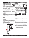
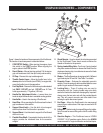
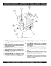
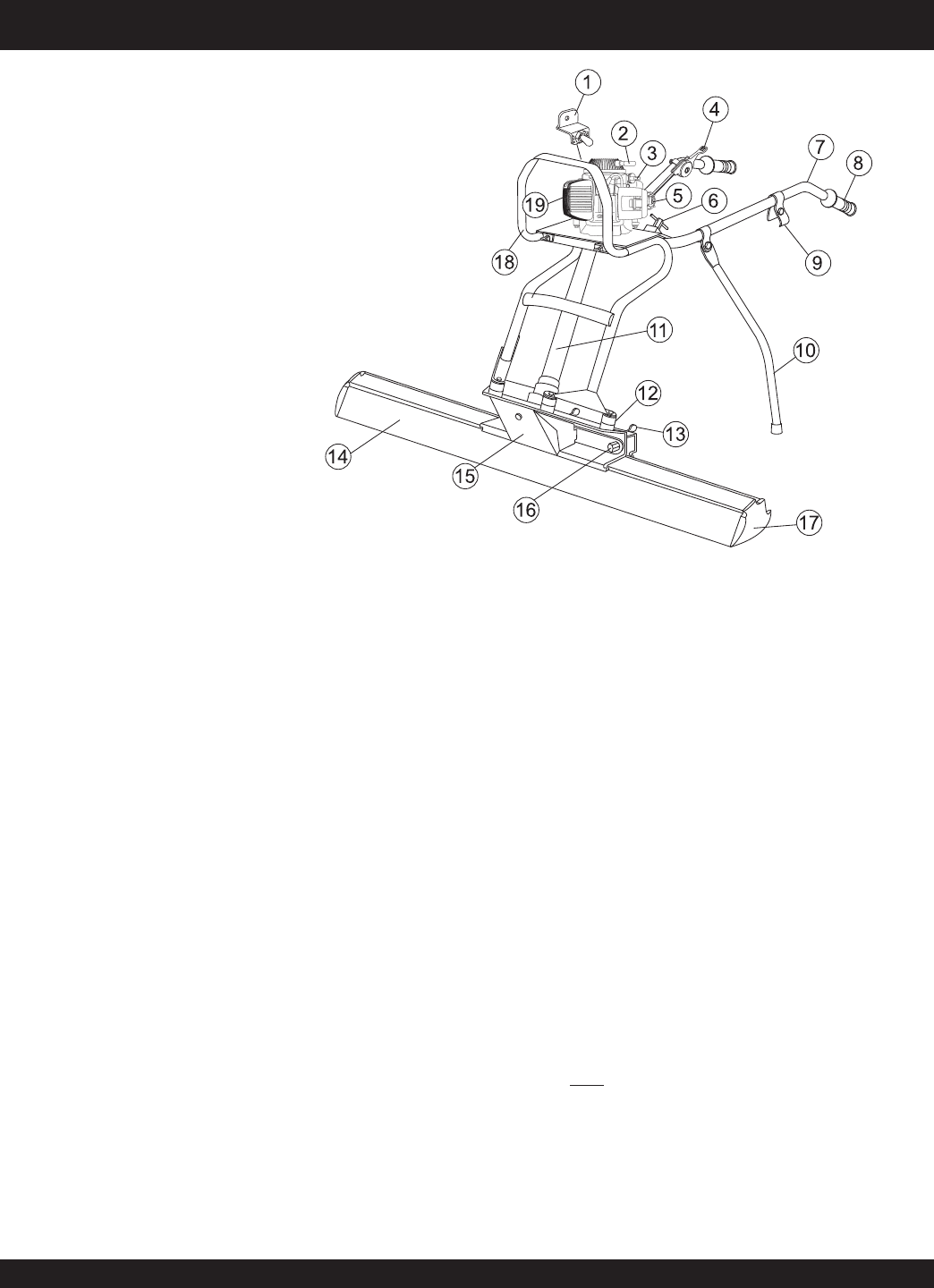
Figure 2. DuoScreed Components
Figure 1 shows the location of the components of the DuoScreed.
The function of each component is described below:
1. START/STOP Switch – When starting the engine, place
this switch in the START position. When stopping the
engine, place in the STOP position.
2. Recoil Starter – Manual-starting method. Pull the starter
grip until resistance is felt, then pull briskly and smoothly.
3. Oil Cap – Remove this cap to add engine oil.
4. Throttle Control Lever – Move the throttle lever to the
down
position for full throttle (max RPM's), for engine idle,
move the throttle lever to the
up
position.
5. Fuel Cap/ Tank – Remove the fuel tank cap to add unleaded
fuel ONLY! DO NOT mix fuel. DO NOT over fill. Tank
holds approximately .172 gallons (.65 liters).
6. Handle Bar Adjustment Knobs – Loosen these two
knobs to adjust the handle bar to a suitable working position.
7. Handle Bar – Used in the steering of DuoScreed.
8. Hand Grip – When operating the DuoScreed use this hand
grip to maneuver the machine.
9. Support Stand Latch – Use this latch to lock support
stand in place when DuoScreed is in operation.
10. Support Stand – Use this stand to support the DuoScreed
when not in use.
11. Flexible Drive Shaft– Connected to the drive shaft of the
engine, provides the vibrational force for the eccentric
weights.
12. Shock Mounts – Used to absorb the vibration generated
by the DuoScreed. These shock mounts minimize the
transfer of vibration to the operator.
13. Spring-Loaded Wing Nuts– Turn these 3 spring loaded
wing nuts counterclockwise to release the blade from the
aluminum clamping strip, turn clockwise to secure the blade
to the clamping strip.
14. Blades – The DuoScreed can be equipped with 2 different
type blade styles HD and LW. See Table 1 for details.
15. Eccentric Cover – Encloses the adjustable eccentric
weights. Press the spring clip tab inward and slide the cover
upward to gain access to the eccentric weights.
16. Locking Nuts – These 3 locking nuts are used in
conjunction with the 3 spring loaded wing nuts which
secure the blade to the aluminum clamping strip. Important!
always cover the two outer nuts with the provided plastic
cap. This will prevent concrete and other debris from
entering the quick disconnect system.
17. End Caps – Allows the DuoScreed to be maneuvered
around pipe or obstructions. End caps are used with HD
blades
only.
18. Lifting Bar– This bar is only for manual lifting on the jobsite.
Not to be used for manual lifting with a forklift or other lifting
device.
19. Gasoline Engine – This DuoScreed uses a HONDA
GX35SAT 1.6 HP gasoline engine. Refer to the
HONDA
owners manual for engine information and related topics.