


PAGE 32 — DCA20SPXU2 (WITH MLT20 SERIES) • OPERATION AND PARTS MANUAL — REV. #0 (01/18/13)
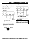
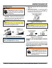
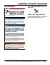
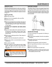
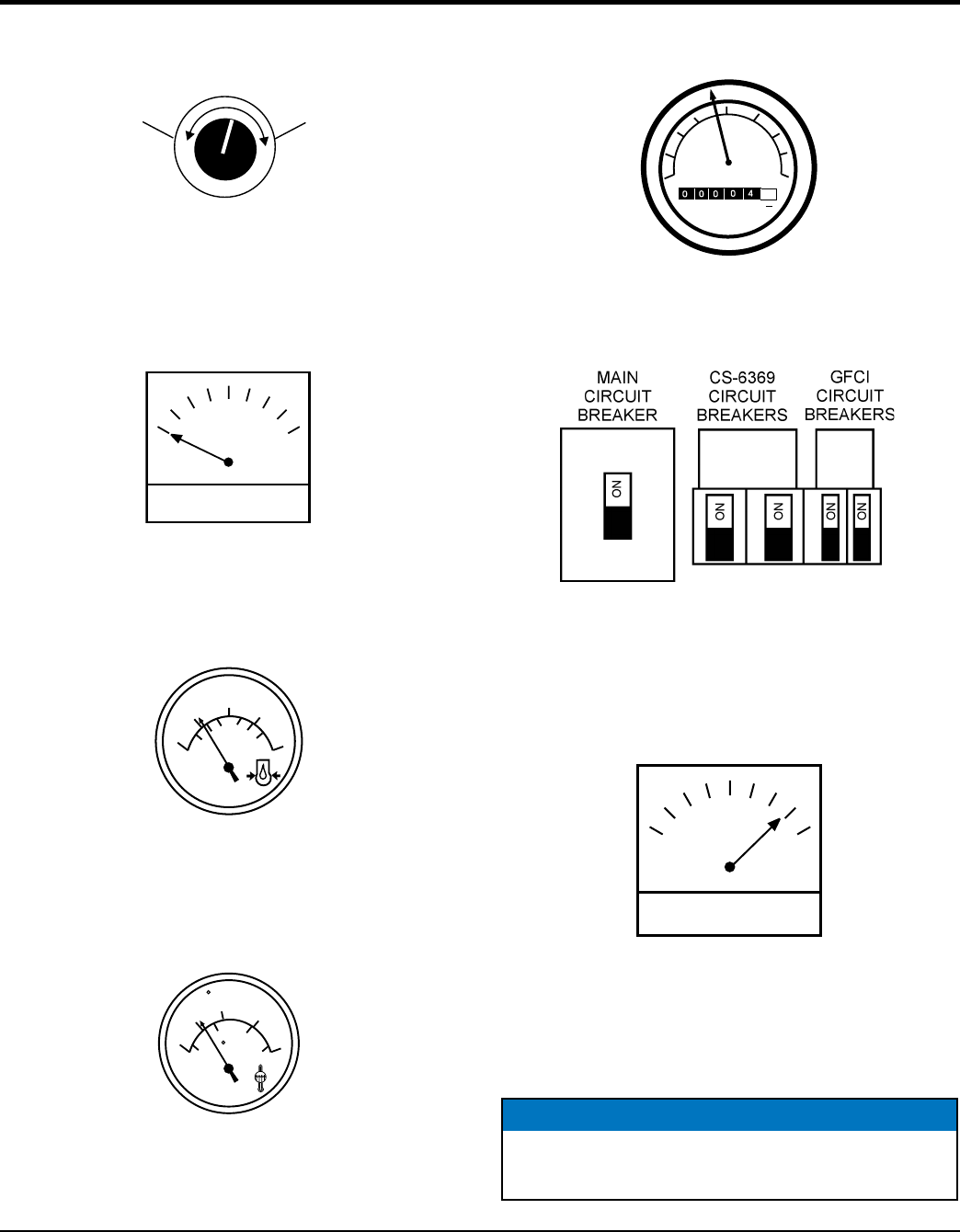
5. If the voltage is not within the specified tolerance use
the voltage adjustment control knob (Figure 29) to
increase or decrease the desired voltage.
Figure 29. Voltage Adjust Control Knob
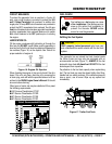
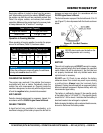
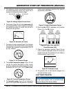
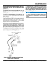
6. The ammeter (Figure 30) will indicate zero amps with
no load applied. When a load is applied, the ammeter
will indicate the amount of current that the load is
drawing from the generator.
Figure 30. Ammeter (No Load)
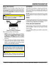
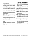
7. The engine oil pressure gauge (Figure 31) will indicate
the oil pressure of the engine. Under normal operating
conditions the oil pressure is approximately 35 to 65
psi. (241~448 kPa).
Figure 31. Oil Pressure Gauge
8. The coolant temperature gauge (Figure 32) will
indicate the coolant temperature. Under normal
operating conditions the coolant temperature should
be between 180°~221°F (82°~105°C) (Green Zone).
Figure 32. Coolant Temperature Gauge
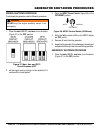
9. The tachometer gauge (Figure 33) will indicate the
speed of the engine when the generator is operating.
INCREASE
DECREASE
A
50
75
100
0
25
1
2
3
4
5
6
bar
OIL
PRESS
psi
DATCON
150
180
240
100
130
40
C
WATER
TEMP
DATCON
60
80
110
F
Under normal operating conditions this speed is
approximately 1800 RPM’s.
Figure 33. Engine Tachometer Gauge
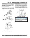
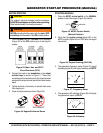
10. Place the main, G.F.C.I., and aux. circuit breakers
(Figure 34) in the ON position.
.
Figure 34. Main, Aux. and GFCI
Circuit Breakers (ON)
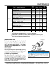
11. Observe the generator’s ammeter (Figure 35) and
verify it reads the anticipated amount of current with
respect to the load. The ammeter will only display a
current reading if a load is in use.
Figure 35. Ammeter (Load)
12. The generator will run until manually stopped or an
abnormal condition occurs.
LIGHT TOWER OPERATION
20
25
3010
40
TACH
HOURS
RPMX100
8
1
10
0
35
5
15
0
0 0
0
4
A
NOTICE
For light tower operation, refer to the MLT20 Series
Operation Manual (Part Number 49838).
GENERATOR START-UP PROCEDURE (MANUAL)