


DCA20SPXU2 (WITH MLT20 SERIES) • OPERATION AND PARTS MANUAL — REV. #0 (01/18/13) — PAGE 31
GENERATOR START-UP PROCEDURE (MANUAL)
BEFORE STARTING
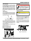
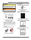
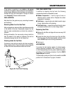
1. Place the main, G.F.C.I., and aux. circuit breakers
(Figure 23) in the OFF position prior to starting the
engine.
Figure 23. Main, Aux. and GFCI
Circuit Breakers (OFF)
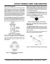
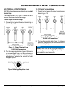
2. Connect the load to the receptacles or the output
terminal lugs as shown in Figure 11. These load
connection points can be found on the output terminal
panel and the output terminal panel’s hard wire hookup
panel.
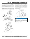
3. Tighten terminal nuts securely to prevent load wires
from slipping out.
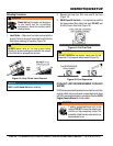
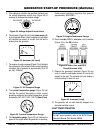
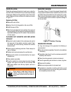
4. Close all engine enclosure doors (Figure 24).
Figure 24. Engine Enclosure Doors
CAUTION
The engine’s exhaust contains harmful emissions.
ALWAYS have adequate ventilation when operating.
Direct exhaust away from nearby personnel.
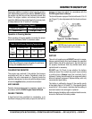
WARNING
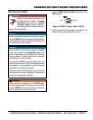
NEVER manually start the engine with the main, GFCI
or auxiliary circuit breakers in the ON (closed) position.
INCORRECT
CORRECT
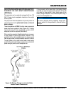
STARTING (MANUAL)
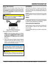
1. Place the MPEC control switch in the MANUAL
position to start the engine (Figure 25) position.
Figure 25. MPEC Control Switch
(Manual Position)
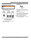
2. Verify that the engine running status LED on the
MPEC module (Figure 26) is lit (ON) after the engine
has started
Figure 26. Engine Running (LED ON)
3. The generator’s frequency meter (Figure 27) should
be displaying the 60 cycle output frequency in HERTZ.
Figure 27. Frequency Meter
4. The generator’s AC-voltmeter (Figure 28) will display
the generator’s output in VOLTS.
Figure 28. Voltmeter
AUTO
MANUAL
OFF/RESET
AUTO
MANUAL
OFF/RESET
LOWOILPRESSURE
HIGHCOOLANTTEMPERATURE
OVERCRANK
OVERSPEED
ENGINERUNNING
MOOOOO-20001Q
Hz
V