


PAGE 24 — MAYCO C-30HDNI (PRECISION) PUMP — OPERATION AND PARTS MANUAL — REV. #7 (04/03/12)
C-30HDNI (PRECISION) PUMP — CONTROL BOX COMPONENTS
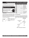
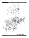
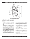
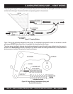
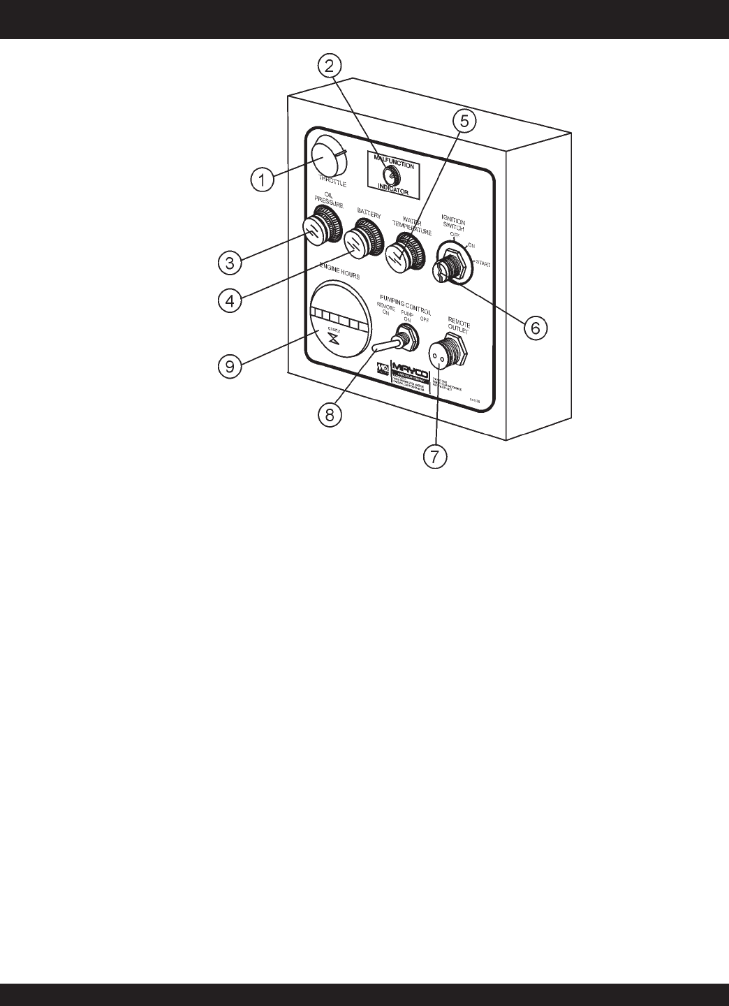
Figure 8. Pump Control Box Components
Figure 8 illustrates the location of the major components for the
C-30HDNI Control Box. The function of each component is
described below:
1. Throttle Control Switch – This is a variable speed type
control. Holding the control switch to the
left
increases the
engine speed. To place the engine at IDLE speed, hold the
control switch to the
right
and let the engine run for 3-5
minutes.
2. Trouble Indicator LED– This is a diagnostic feature on the
C-30HDNI to assist the operator with identifying problems
that occur with the fuel injection system (See Table 7).
3. Oil Pressure Indicator Lamp – In the event of low oil in the
engine crankcase or low oil pressure, the oil "
Oil
Pressure
Lamp
" indicator will be lit. STOP the engine immediately if
this lamp is lit.
NEVER
run the engine when this lamp is on.
4. Battery Charge Indicator Lamp – Indicates if the electrical
system is charging properly. If the "
Battery Charge
Indicator
Lamp
" is lit, this is an indication that the charging system is
malfunctioning. STOP the engine and remedy the electrical
charging problem.
5. Water Temperature Lamp – In the event of high engine
water temperature (220 degrees Fahrenheit), this lamp will
be lit. STOP the engine immediately if this lamp comes on.
NEVER
run the engine when this lamp is on.
6. Ignition Switch – Insert the ignition key here to start the
engine. Turn the key clockwise to the ON position, then
continue turning clockwise to the START position and
release. To stop the engine turn the key fully counter-
clockwise to the
STOP position.
7. Remote Control Input Connector – Insert the remote
control input cable into this connector.
8. Pumping Control Switch – This 3-position switch controls
the pumping of the pump. The
left most
position is for use
with the remote control unit, the
center
position is for off
(prevents pumping), and the
right most
position is for
normal pump operation.
9. Hourmeter– Display's the number of hours the pump has
been in use.