


128-7405
9 of 28
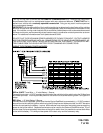
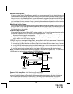
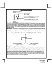
GREEN Wire: Ignition 2 Output
Connect this wire to the ignition 2 wire from the ignition switch. This wire will show + 12 volts when the
ignition key is turned to the "ON" or "RUN" position and is some cases the "START" or CRANK" position.
This wire will show 0 volts when the key is turned to the "OFF" and "ACCESSORY" positions.
NOTE: See programming information (Bank 3 Selection #2) concerning this wire to allow output during the
"START" mode.
VIOLET Wire: Accessory Output
Connect this wire to the Accessory wire from the ignition switch. This wire will show + 12 volts when the
ignition switch is turned to the "ACCESSORY" or "ON" and "RUN" positions, and will show 0 volts when
the key is turned to the "OFF" and "START" or "CRANK" positions.
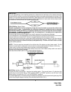
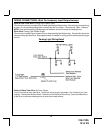
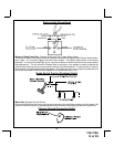
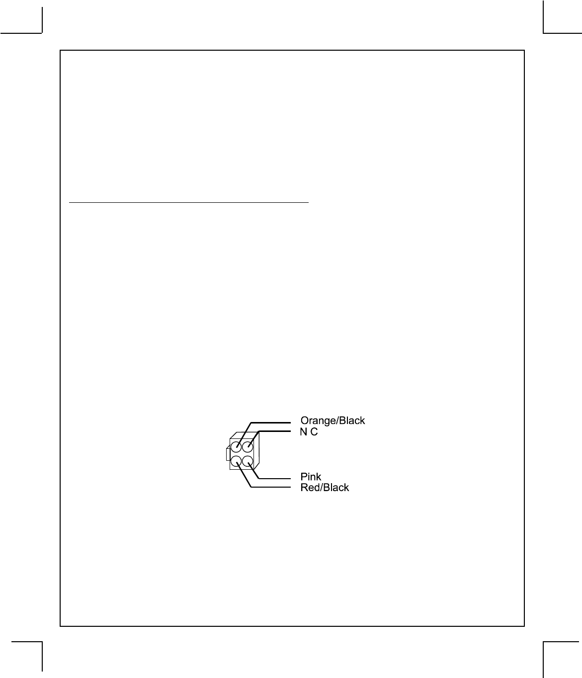
WIRING THE 4 PIN ALTERNATE IGNITION HARNESS
ORANGE/BLACK Wire: Parking Brake Input
This wire is used only when the turbo timer mode, Bank 3, feature # 16 is selected ON. This input insures
that the vehicle parking brake is applied whenever the vehicle is set up for and the turbo timer circuit is used.
This input must switch to ground when the vehicle's parking brake is applied. Connect the Orange/Black wire
to the negative output of the vehicle's parking brake switch.
RED/BLACK Wire: + 12 Volts Input
Note: The Red/Black and Pink are dry contacts and may be used for negative switching when necessary.
Connecting the Red/Black to chassis ground will result in Pink being ground when the R/S is activated.
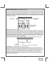
This input is to be connected to a separate, (Other than the wire Red or Red/White is connected to), constant
on + 12 volt source which will supply + 12 volt power to the additional ignition output, (Pink), wire. This should
be a separate + 12 volt source other than the 12 volts connected to Red or Red/White
PINK Wire: Additional Ignition Output
This wire can be used as an additional + 12 Volt ignition output supplied by the Red/Black wire. This output
can be selected to be on or off during the start cycle. (See feature bank 3 selection # 8) Connect this wire
to the third ignition circuit in the vehicle and set the selectable feature # 8 of Bank 3 according to the way
in which the vehicle's ignition switch operates.
9