


128-7405
18 of 28
18
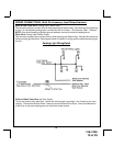
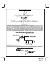
Black w/ Yellow Trace Wire: Ground Output During Start (Crank)
The Black w/ Yellow Trace wire will provide a 300 mA ground output while the starter output of the remote
start unit is active. This output can be used to activate the Crank Low/Bulb Test wire found in some GM
vehicles. This wire is also referred to as the ECM wake up wire in some vehicles.
NOTE: The outputs above are low current outputs and must be used with a relay if the circuit's requirement
is more than 300 mA.
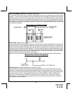
2 Pin Transponder Control Output: (Yellow Connector)
This output is intended to allow the control of a transponder bypass interface module or transponder
bypass relay. The system also allows software selections to control the way in which this output
operates, see remote start feature # 10 for setting this output.
When the unit is selected for output during the start sequence, this output will be active at the same
time Ign. 3 becomes active, and will remain active until the vehicle has started. This will be used for one
time read transponder circuits.
When the unit is selected for transponder on, this output will become active at the same time ign. 3
becomes active, and will remain active all the time the unit is operational under the control of the remote
start. When the unit is selected for continuous and the vehicle is started via the Remote Start, this
output will become active at the same time ign. 3 becomes active and will remain active until the ignition
in the vehicle goes low. This will allow the unit to be used for continuous read transponders circuits.
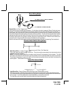
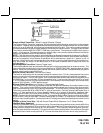
2 Pin Control Switch: (Red Connector)
The Black & Black w/White Trace wires loaded in the two pin red connector enable the operation of the
Remote Start unit. When the Black w/ White Trace wire is grounded, the remote start unit is operable.
When this wire is open from ground, the remote start is disabled. Route the twin lead Black & Black w/
White Trace wires from the control switch to the remote start unit and plug red two pin connector into the
mating red two pin connector shell of the control module.
4 Pin Upgrade Telematic Module:
Red = + 5 Volts / Black = Ground / White = Data TX / Yellow = Data RX
Connect the 4 pin harness found in the Telematic one way module kit to the mating port on the controlling circuit.
NOTE: If using the TWO WAY Telematic module, only Ground, TX, and RX are used on this port, the + 12 volt supply
for the two way module must be sourced separately or the unit will not operate.
2 Pin Valet/Program/Override Push-Button Switch: (Blue Connector)
The Black & Grey twin lead wires loaded in the two pin blue connector are the ground supply and program/
valet/override input of the Remote Start unit. When the Grey wire is grounded, under certain conditions, the
unit will enter the valet mode. When the Grey wire is sequentially grounded under other conditions, the unit
will enter the various program modes. Route the twin lead Black and Grey wires from the valet/Program
switch to the remote start unit and plug the two pin connector into the mating blue connector shell of the
control module. Refer to the remote programming, feature programming and function programming shown
later in this installation guide for operation of the valet/program switch. For override information, refer to the
owners manual.
4 Pin Antenna/Receiver Connector:
Plug the previously routed connector from the antenna receiver assemble into the mating connector of the
control module. This connector supplies 12 volts, ground and RF data from the antenna receiver to the
remote start module. Be certain this connector is firmly seated making good contact to the control unit.
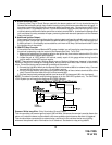
4 Pin Shock Sensor: (White Connector)
The Red (+12 volt), Black (ground), Blue (pre-detect) and Green (full trigger when armed) wires loaded into
the white connector shell are the inputs/outputs of the shock sensor. Route the 4 wire harness from the
shock sensor to the remote start control unit and plug the 4 pin white connector into the mating 4 pin
connector shell of the control module.
NOTE: While operating under the control of the remote start unit the shock sensor will be shunted (by-
passed). Once the remote start shuts down, the shock sensor will be re-enabled.
2 Pin LED Harness: (White Connector)
The Red & Blue wires loaded into the two pin mini white connector control the anode and cathode of the
dash mounted LED. Route the twin lead Red and Blue wires from the LED to the remote start control unit
and plug the two pin connector into the mating white mini connector shell of the control module.
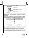
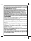
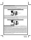
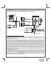
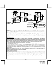
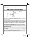
3 Pin Door Lock/Unlock Harness: (White Connector)
The Red and Green wires will provide either a pulsed ground output to the factory door lock control relay, or
a pulsed + 12 volt output to the factory door lock control relay. In either case, the maximum current draw
through these outputs must not exceed 300 mA. The Red w/Black trace wire will provide a pulsed ground
only, and will only provide an output when the unlock button of the transmitter is pressed a second time
after a first unlock command was issued. This is used for second step unlock or all doors unlock in a two
step circuit. In this arrangement, Red is used to control the drivers door unlock relay, and the Red/Black
will be used to control unlock of all other doors.