


128-7405
15 of 28
15
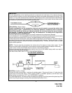
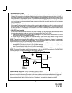
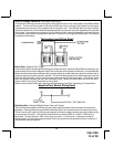
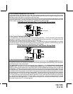
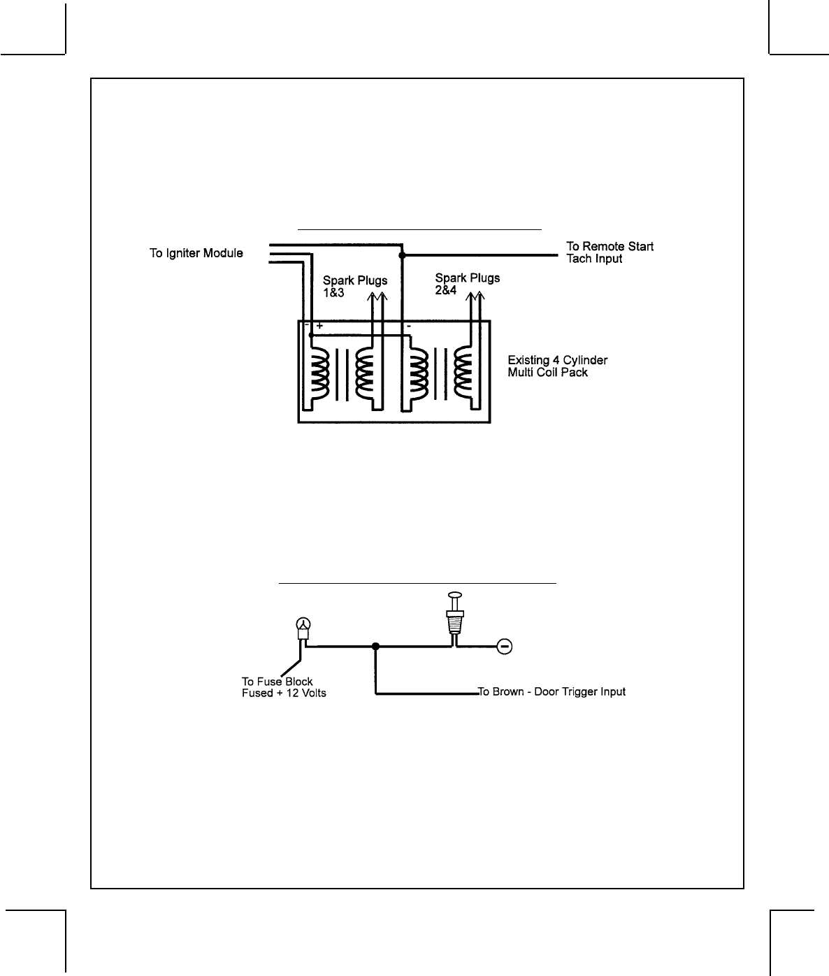
Green w/ Orange Trace Wire: Tachometer Input Signal
This wire will continually monitor the engine's tach rate while the unit is under power of the Remote Start
module. This wire will be routed to the vehicle ECM tach input or through the firewall into the engine
compartment and connect to the negative side of the ignition coil. This Remote Start unit learns the tach
rate of the vehicle and in most cases will operate properly from one multi coil pack regardless of the number
of cylinders. If the vehicle has a single coil unit for each cylinder, it may be necessary to connect this wire
to more than one cylinder for proper tach reference. See multi coil wiring detail shown later in this manual
for additional information.
Tachometer Input Wiring Detail
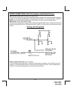
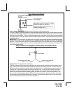
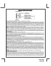
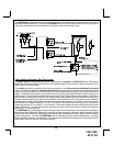
Brown Wire: Negative Door Trigger
If the vehicle's door courtesy light switches ground when the door is opened, (Most GMs and Imports), you
must connect this wire to the negative output from one of the vehicle's door pin switches. In most cases the
Brown wire will need to be connected to only one door switch no matter how many doors the vehicle has as
most door lighting circuits are wired in parallel. This wire will be shunted when remote starting the vehicle
and will remain shunted, if active, while running under command of the remote start. If this wire is active
when the system is armed, the siren will emit three chirps. When the zone clears, the siren will emit 1
chirp to confirm full arming. See below for wiring detail.
Note for vehicles with interior delay lighting see programming under title "Completing The Installation".
Negative Door Switch Wiring Detail
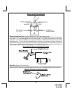
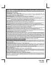
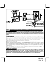
Dark Blue Wire: Delayed 300mA Pulsed Channel 3 Output
The Dark Blue wire supplies a 300mA ground pulsed output whenever channel three of the receiver is
accessed. Pressing the pre-programmed transmitter button for three seconds will access channel two.
This is a low current output and must be connected to a relay to supply power to the trunk release or the
circuit you wish to control. Connect the Dark Blue wire to terminal # 86 of a VF45F11 P&B relay or
equivalent. Connect terminal # 85 of the relay to a fused + 12 volt source. Connect the common,
normally open, and normally closed contacts of the relay to perform the selected function of channel 3.
See below for relay wiring detail.